Continue to Site

Eng-Tips is the largest engineering community on the Internet

Intelligent Work Forums for Engineering Professionals

  • Congratulations cowski on being selected by the Eng-Tips community for having the most helpful posts in the forums last week. Way to Go!

Precision Milling Machine Foundation on Poor Soil

Status
Not open for further replies.

bones206

Structural
Jun 22, 2007
1,998
Background:

I'm designing a foundation for a high-precision CNC lathe unit. It weighs about 70,000 lbs and will be installed in an existing building. Based on prior experience at this site, I'm expecting a uniform fill layer of very loose sandy gravel between 8 and 20 ft down to ledge. We've seen excessive settlements and inexplicable voids/sinkholes during excavations for new foundations in past projects at this site. The ledge slopes and the site pad was brought level with fill sometime prior to 1960. Our geotech has historically never gone higher than 1,500 psf allowable bearing for anything to be founded on the sandy gravel at this site.

Question:

Does anyone have experience using post-tensioned rock anchors to provide stability and movement control for a high-precision machine foundation pad? The manufacturer's drawings indicate a super thick (~5 ft) foundation, but say final design is based on site conditions and EOR's judgement. My thought is that a 2 ft thick slab with some post-tensioned rock anchors would be more constructible, given the space constraints within the building. But it's more of a hunch at this point and I'm curious if anyone has experience with this approach.

 
Replies continue below

Recommended for you

Whenever I've needed to do foundations for these high precision machines, I've put them on deep foundations because our soils around here are clay for 50 feet, glacial till overlaying bedrock. For 20 feet of fill materials, I'd be looking at deep foundations as well.
 
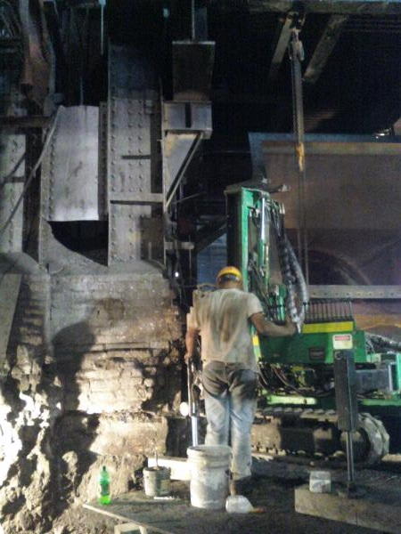
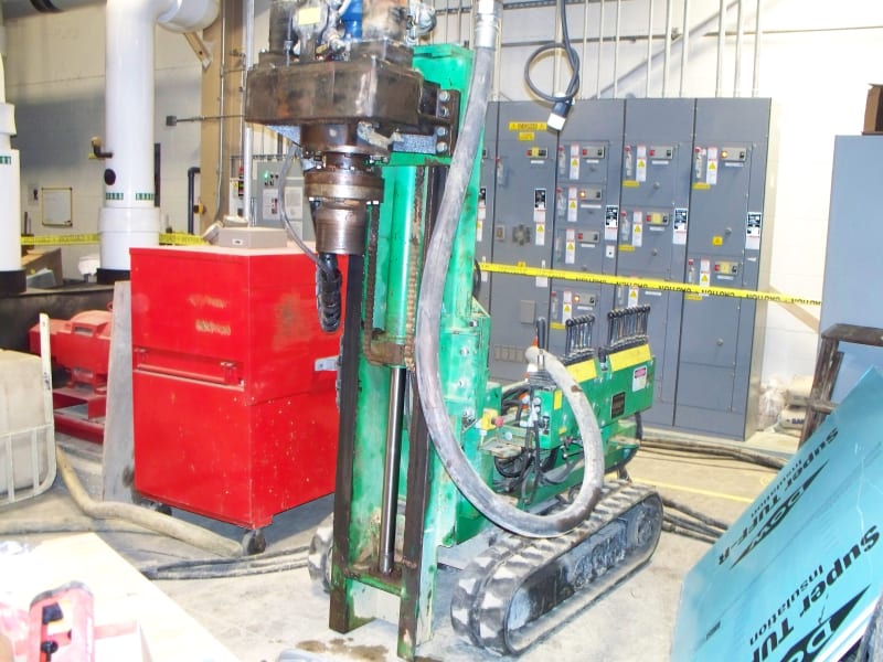
Thanks jayrod. I've used cased micropiles for other structures at this facility, but in those cases I had more headroom and space to work with and the drilling rig was about the size of a typical excavator. With this CNC machine, I will be in tight quarters and low headroom near another existing CNC machine that is in daily use. So I'm looking for a solution that can use smaller equipment with less disturbance.

I found this video on Youtube, which is almost the exact same situation that I have. Similar building and even the same CNC manufacturer. The video description says they used hollow bars, but I'm not overly familiar with those. Does the hollow bar system get anchored to the rock, then post-tensioned to provide a stable, compressed bulb of soil below the foundation pad? Or is it more like a typical micropile system that creates a vertical load-bearing column to support the foundation block?

Screenshot_2022-05-26_135852_bti9xw.png
 
You should go deep; there's no way to accommodate loose fill. Check with local foundation guys to see if you can use micropiles. If not can you use screw piles. I've used them for significant loads... worst case was six 400,000 lb transformers. Locally, we have soils like jayrod... You will not likely accommodate it by using a thick slab, unless you can live with the entire thing tilting. How far down is bedrock?

On poor soil, I don't see how post-tensioned rock anchors can help... I've used them for lots of other stuff...

Rather than think climate change and the corona virus as science, think of it as the wrath of God. Do you feel any better?

-Dik
 
I monitored micro-pile installation with a low clearance rig. It would fit through a single man-(person) door. The mast was only about 6 to 8 feet tall.

I think your answer is deep foundations.
 
Thanks for the replies jayrod, dik and TigerGuy.

I'm pretty sure I'll be going with some sort of micropile for this project, depending on what pile system the goetech recommends. I've also decided that post-tensioning is not likely something I need consider here. Not sure why I thought that to begin with - just an erroneous intuition I guess.

I'm hoping to get some more design criteria from the CNC manufacturer such as allowable differential settlement and possibly max. vibration amplitudes. I'm sure these Okuma machines have strict requirements in order to perform properly and avoid re-calibration/re-leveling, but I've yet to see anything in writing, which is why I was reaching out here to see if anyone had prior experience.
 
On the topic of deflection criteria for a PMM, the only thing I've ever seen was absolutely insane. I feel it was in the range of 0.2mm per metre. Ended up with a hugely thick raft slab supported by a series of deep piles.
 
Thanks jayrod - that's a useful point of reference.
 

It worked really well with Millennium Towers...

Rather than think climate change and the corona virus as science, think of it as the wrath of God. Do you feel any better?

-Dik
 
dik said:
It worked really well with Millennium Towers...
To be fair, wasn't a giant concrete tower sitting on top of it. And it was piles driven to refusal which, as you're aware, locally is on till or sometimes bedrock at around 40-50 feet down.
 
The criteria important for the milling machine is stiffness needed to keep the machined product in tolerance. Most lathes particularly large ones do not have enough structure to provide the required stiffness, so they depend on the foundation to provide it.
If you sit the foundation on bedrock, you can assume the bedrock is very stiff.
If your foundation sub structure extends only into softer stuff, from the standpoint of the machine, the softer stuff is a spring, so the machine foundation needs to provide more stiffness. The 5 foot foundation recommendation does not surprise me, as the thickness provides more stiffness.

jayrod12 indicated 0.2mm per metre is his expectation. Having aligned several large machine tools, his number is likely close, we used an old school method using 3 foot precision levels, and were satisfied with about 0.0005 inch per foot. Fortunately final leveling does not depend on the concrete finish. Good leveling wedges should be part of the kit, they are simpler to use than the more traditional shims, and make future adjustment easier. For the wedges to work, the concrete foundation must be much stiffer than the machine.
Screenshot_from_2022-06-19_17-15-49_solvg9.png


Some references
thread194-470761
 
This unit has threaded sleeves that jack against the anchor bolts to adjust for level. I see the logic in providing a stiff foundation for those screws to jack against, but I'm still unsure how to quantify that and what criteria to compare against.

I'm having borings done soon, and I'm planning to ask for calculated spring values for the micropiles as part of the geotech report. I have a pretty detailed RISA model of the foundation and can model the piles as springs in the model to get an "accurate" estimate of the deflected shape under load. Would it be sufficient if I can show that the deflected shape stays below 0.0005 in/ft ? That was my original approach to this, but I feel like a calculated pile stiffness is a very rough estimate, being used to predict a very fine deflection value.
 
Just to follow up, I ended up with a 36" thick foundation with 5.5" cased micropiles spaced roughly 5'-9" apart. Bedrock was confiremd by borings about 10' down.

I did a RISA Foundation model with the actual anchor layout point loads, and was able to stay within the 0.0005 inch per foot deflection mentioned by FacEngrPE using a 30" slab (including RISA's default stiffness modifier for cracking). I added 6 more inches for good measure and to account for the pile embedment.

I'll try to give another update after the install is complete.
 
Status
Not open for further replies.

Part and Inventory Search

Sponsor