Hello,
I am currently evaluating the performance of a swirl burner. I got two lines going into the burner rig, (1) a methane line that comes from a pressurized cylinder and (2) a compressed air line. Each going through a needle valve and a rotameter. Currently there are no manometers after the rotameters. I am unsure if I should consider the operating pressure of the rotameter as (almost)atmospheric or if the operating pressure would be different than that. Is a manometer after the rotameters needed? As I turn the needle valve will the pressure in the rotameter increase considerably? Could it possibly reach the pressure from before the needle valve? Unfortunately I do not have the specifications for the needle valves.
I'll give as much information as possible for each line:
Methane line:
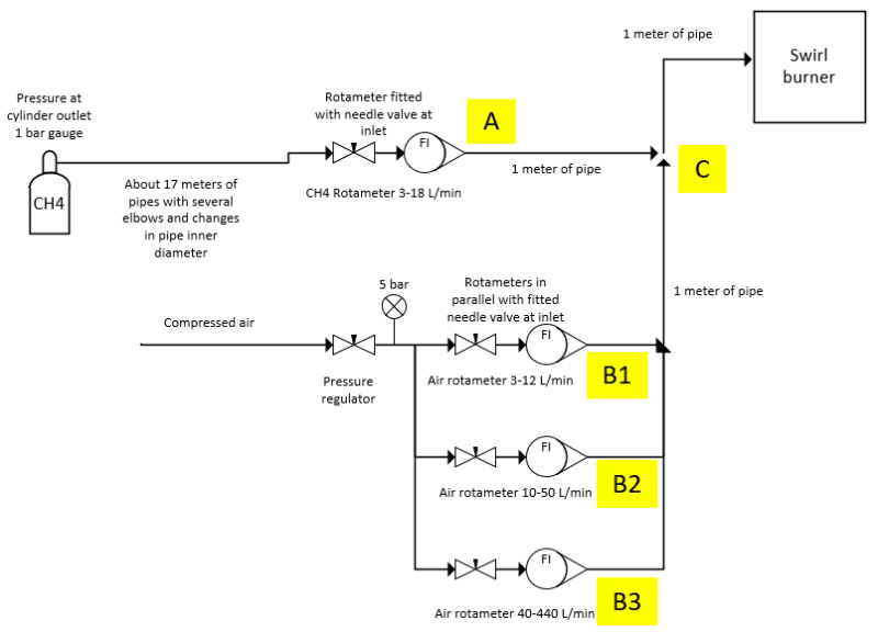
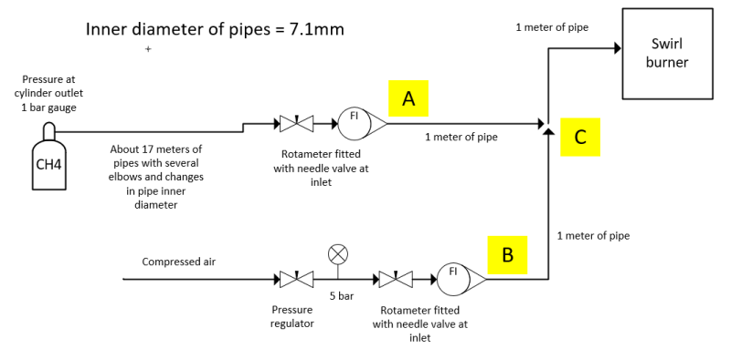
The pressure at the outlet of the gas cylinder is at 1 bar gauge, the line runs for about 17 meters of piping and elbows before passing through a needle valve and a rotameter. After the rotameter, the line goes through about 1 meter of piping and mixes with the air line.
Scale in the rotameter is at standard conditions. Volume flow rates through this line (as measured by the rotameter) vary from 3 liters/minute up to 18 liters/minute. Pipe inner diameter is 7.1mm
Air line:
The compressed air pressure is regulated to 5 bar gauge before passing through a needle valve and a rotameter. The lines then goes through about 1 meter of piping and mixes with the gas line.
Scale in the rotameter is at standard conditions. Volume flow rates through this line (as measured by the rotameter) vary from 10 liters/minute up to 100 liters/minute. Pipe inner diameter is 7.1mm
Methane+Air line
After the mixing point, the gas mixture goes to the swirl burner and is ignited. Burner is unconfined (i.e. open to the atmosphere). Pipe inner diameter is 7.1mm
A diagram of the setup is
Any help would be highly appreciated.
I am currently evaluating the performance of a swirl burner. I got two lines going into the burner rig, (1) a methane line that comes from a pressurized cylinder and (2) a compressed air line. Each going through a needle valve and a rotameter. Currently there are no manometers after the rotameters. I am unsure if I should consider the operating pressure of the rotameter as (almost)atmospheric or if the operating pressure would be different than that. Is a manometer after the rotameters needed? As I turn the needle valve will the pressure in the rotameter increase considerably? Could it possibly reach the pressure from before the needle valve? Unfortunately I do not have the specifications for the needle valves.
I'll give as much information as possible for each line:
Methane line:
The pressure at the outlet of the gas cylinder is at 1 bar gauge, the line runs for about 17 meters of piping and elbows before passing through a needle valve and a rotameter. After the rotameter, the line goes through about 1 meter of piping and mixes with the air line.
Scale in the rotameter is at standard conditions. Volume flow rates through this line (as measured by the rotameter) vary from 3 liters/minute up to 18 liters/minute. Pipe inner diameter is 7.1mm
Air line:
The compressed air pressure is regulated to 5 bar gauge before passing through a needle valve and a rotameter. The lines then goes through about 1 meter of piping and mixes with the gas line.
Scale in the rotameter is at standard conditions. Volume flow rates through this line (as measured by the rotameter) vary from 10 liters/minute up to 100 liters/minute. Pipe inner diameter is 7.1mm
Methane+Air line
After the mixing point, the gas mixture goes to the swirl burner and is ignited. Burner is unconfined (i.e. open to the atmosphere). Pipe inner diameter is 7.1mm
A diagram of the setup is
Any help would be highly appreciated.