Continue to Site

Eng-Tips is the largest engineering community on the Internet

Intelligent Work Forums for Engineering Professionals

  • Congratulations KootK on being selected by the Eng-Tips community for having the most helpful posts in the forums last week. Way to Go!

Pressure at tank bottom

Status
Not open for further replies.

DRQ

Agricultural
Feb 18, 2020
9
Hi,

I am trying to understand what a certian pressure at the bottom of a tank would be.
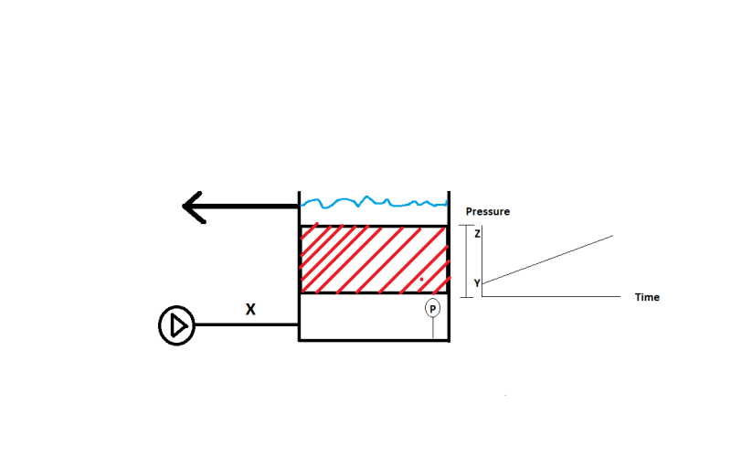
I have attached a drawing trying to sketch the problem.

The pump is pumping water in at at the bottom with a fixed volume/hr and pressure .
The water then travels through some biomedia which results in a pressure loss Y, this loss increases to pressure loss Z over time but let us assume a pressure of X.
And the of course the water column with a pressure of W.

What would the pressure transducere show at a given time?
Tank_ljgqov.png


Thanks
 
Replies continue below

Recommended for you

Pressure X plus whatever the head difference is between your pipe and the tank floor.

But where are you measuring pressure X?

Remember - More details = better answers
Also: If you get a response it's polite to respond to it.
 
Hi LittleInch,

Thanks for the quick reply.

The pressure trancducer is used to meassure the water level in the tank, but inspite of my recommendations they also want it to control the pump.


Thanks again.
 
First, X will always read at least W + pressure loss across the filter = W + delta_F.
Secondly, if the pump can supply more pressure than W, say W+ p, flow will start through the filter and delta_F will begin to increase with flow passing through the filter resulting in P reading W + delta_F, which will also equal = X + the pressure equivalent of the distance from pump discharge elevation to the tank floor.

It should be no problem to use P's reading for controlling the pump's discharge pressure provided that you set it for the pressure corresponding to the level in the tank W + delta_F, deltaF being equal to the pressure drop across the filter when flowing at some discharge rate Q. If Q will be constant, it is pretty easy. If Q will vary, then you will need to develop an appropriate delta_F vs Q relationship to add to W.


It boils down to this: Do you want pressure control with a feed worward based on the bio bed d/p. In part it depends on your pump design, it's min flow requirements, and whether you have a pupmp recycle valve or a variable speed pump.

It is a can of worms as a forum response. Design the process first, if that is not possible at this point, it will be trial by error design. Good luck.
 
What kind of pump is used? If you're not using a positive displacement pump I'd think the following:

Over time the flow resistance will increase, hence your operating point moves to a greater head / lower flow rate, hence X will change. So it could be used to control the pump. Except for the additional static head it does not really differ from measuring pressure in the pipe between the pump and the tank or after the tank.
 
Well you then need to subtract the pressure from the pump to establish water height, but given the variable pressure drop in your filter, it might not work to measure level.

In fact it won't work for level.

Radar guage instead?

Or measure the pressure above the filter to get the water level above the filter.

Remember - More details = better answers
Also: If you get a response it's polite to respond to it.
 
? Pressure at any point above the filter is always constant, given it is an open tank, like the diagram shows. Why measure that.

? Level is also apparently controlled by the outlet nozzle elevation. Why measure that?


I guess the diagram is simplistic and maybe level does vary and there is a valve on the outlet.

However if the pressure below the "biomedia" changes over time, it won't be possible to use a PT on the tank bottom to calculate level as you won't know if the extra pressure is due to extra level or just extra DP across the "biomedia"

PS third name change this week?

Remember - More details = better answers
Also: If you get a response it's polite to respond to it.
 
If you want to run at constant P, then you will have to accept a somewhat variable flow rate, until max delta_F is reached, flow decreasing as filter catches whatever it is catching, then you can use P_max to do that. Just set P for max pressure = W + delta_F_max, when the filter is at delta_F_max, ie. when P is also max, trip a change, or wash, or backwash the filter light.

If you want to run at a given flowrate, then do it right, i.e. from a flow control setup using a flow indicator as direct input to pump rpm control.

 
Hi all,

Thanks for the great discussion, just to clarify what this is used for:

This is a bio filter with biomedia in the red area, this area will get gunked up with all kinds of stuff during operations over time.
The whole idea here is that there is a constant volume pumping through it all the time, no variations, this is controlled by a flowmeter (my bad for not mentioning this).
When the pressure drop across the medium gets to big, a cleaning cycle will start.
During this cycle the pump will shut down, the water column lowered, and air injected to move the media around and clean it.

My concern here is/was if the pressure transducer will see the increased pressure required to pump through the filter or what it actually will read.

Hope this helps.

Again thanks for the help.
 
Yes it will see the pressure rise and IMO you should set the pump to turn off and the cleaning sequence to begin just before you get to some safe maximum operational tank level, at which P = W_max + delta_F_max, delta_F_max being the maxium pressure drop across the filter that you will allow before cleaning is required.

Be sure that your pressure transducer remains clean and free from plugging with whatever biotic you're catching there. If they settle towards the bottom, put it as high up from the tank floor as you can. Maybe in the area just below the filter. If not clean it on a regular basis. Another water level limit switch to shut down the pump before tank hi-hi level is reached would be a nice overflow prevention measure.

 
Can you revise your diagram to show us where the other pressure guage is that you're using to measure the DP across the filter?

Does the water level actually change if the flow is constant?

Remember - More details = better answers
Also: If you get a response it's polite to respond to it.
 
Have you considered the structural forces that the pressure drop has on your bed? If this is a fluidized bed the pressure will not change as it gets "gunked-up". If not you need to hold the bed down and design the tank for pressure.
 
Hi LittleInch,

there is not any seconday pressure gauge to meassure the drop over the filter. The idea is to use the tranducer at the bottom of the tank to meassure the increase in pressure from the pump.
As i understand from the posts above, it will see P = W_max + delta_F_max, delta_F_max being the maxium pressure drop across the filter.


Thanks again!
 
Then you can't use it to determine height of the water in the tank.

It only works to understand pressure drop when the water level is fixed.

A lot depends on what the pressure drop is? Metres of water or more?

Remember - More details = better answers
Also: If you get a response it's polite to respond to it.
 
That can be calculated from hydrostatics. P - height to filter x density is the pressure at bottom of filter. 0 + depth to filter x density is the pressure just above the filter.

Even if the water level rises or falls, it will add, or subtract that same pressure diffeential to each and every point below, hence pressure drop across the filter is independent of any change in water level. That only depends on the amount of sludge caught in the filter.

 
But there's only one pressure measurement.

If you have two variables (pressure drop across the filter and height of water in the whole vessel above the filter, how can you determine which of those is causing your single pressure measurement to rise?

Only if one of those is fixed can you work out the other.

Remember - More details = better answers
Also: If you get a response it's polite to respond to it.
 
If you have to have the accuracy within a psi or two, of which I'm not convinced that is necessary; it could probably work with a wider range. then the secret is to design the tank outlet so that water level remains constant, or nearly so, across your range of flow rates. You could do that with a float driven gate if you had to, but I think the right size pipe, not flowing full, could work, because flow would increase up to around 60% d. Or you might make a triangular weir to weld in front of the outlet, etc. That just depends on the range of flow rates you have to deal with and the tank's freeboard you have. You might could change that too. Or just give up on that approach and put another gage in there. I think that really isn't necessary though.

 
If we get enough details, heck, we could design it for him, but I'd rather drink another beer. What about an inverted pyramid tank ??? Oops! Too much beer.
 
Status
Not open for further replies.

Part and Inventory Search

Sponsor