Eng-Tips is the largest engineering community on the Internet

Intelligent Work Forums for Engineering Professionals

Pressure control on vent lines

Status
Not open for further replies.

EG_proc

Chemical
May 16, 2024
15
0
0
IT
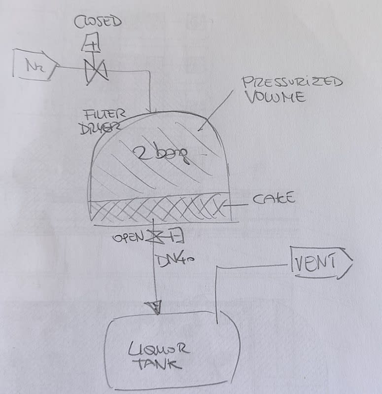
My Client (a chemical production plant) has an issue with the vents from filter dryer mother liquor tank. During the solid/liquid separation they operate the filter dryer with nitrogen at 2 barg and collect the liquid in the tank. At the end of the process a crack may form in the filter cake, hence there is a high pressure nitrogen stream going directly to the vent line, causing issues to the cryogenic treatment installed downstream.
They are asking for a solution to solve this problem.

My approach is the following, but I have a few doubts:
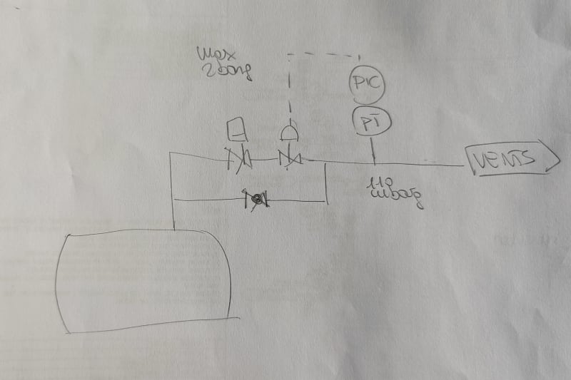
- I calculate the pressure drop of the vent line (new pipe) to the main vent line (existing pipeline, no data available). I get 110 mbar for a DN25 pipe for 100 kg/h nitrogen (flow rate assumed from filter dryer data)
- I consider 110 mbarg as the minimum pressure I have to keep on the vent line to reach the vent treatment system
- I have to control the pressure on the vent line with pressure control valve and pressure transmitter. Which is the pressure I have to consider in the tank for the control valve sizing? I cannot consider 2 barg because there is no control valve able to decrease pressure from 2 barg to 110 mbarg, hence I guess I need to assume a lower pressure upstream the valve. But which criteria can I assume to define this sizing pressure? Also, probably I have to install also an orifice for further pressure drop.

Anyone can help on this?

Many thanks in advance.
 
Replies continue below

Recommended for you

there is no control valve able to decrease pressure from 2 barg to 110 mbarg
Why? You believe there is no CV having dP=1.9 bar, correct?
 
Hi Shvet,
This is what I have been told from my instrumental department.
Moreover, I do not think it would be the best option because if I consider 2 barg as sizing pressure, the control vale would not start closing before 2 barg, hence I would still have a high pressure stream if I had nitrogen let's say at 1.5 barg. The vent stream shall arrive to the cryogenic treament almost at atm pressure.
Probably I should back-calculate the pressure from a reasonable pressure value downstream the control valve, but I am stuck on the criteria. For example:
- pressure of the vent 110 mbarg = pressure downstream control valve (or downstream an orifice if needed)
- reasonable pressure drop of the control valve for 100 kg/h nitrogen = ??
- then I can calculate the max pressure I can allow in the tank during this operational phase of the filter dryer (which is the sizing upstream pressure of the control valve)
 
Could you provide a diagram of your system or at least explain it better.

So you have a belt filter dryer that uses nitrogen as the drying medium? The nitrogen flows through the filter cake at 100 kg/hr under normal drying conditions, then out 1" diameter vent pipe to an existing vent at a pressure drop of 110 mbar, while any liquid flows out of a drain below the belt to the liquor tank? So when a crack develops in the cake full pressure nitrogen flows through the crack and out through the liquid drain directly into the tank and then exiting vent?

I don't understand what you will do with the contol valve to maintain pressure. How will this solve the problem?
 
@EG proc
Have you a process engineering background? Looks like you do not understand how CVs work.
You have been tasked to provide flowrate peak shaving. This can be done by excess flow buffering or diverting.
 
Hi,
Can you release the gas stream to atmosphere or other location? If yes, install a gas liquid separator between the filter and the mother liquor tank. Cracks in the cake are very common and generate by passes.
My 2 cents
Pierre
 
Sketch required. Show liquor tank vent line also and how it is connected to filter dryer vent. Also explain what should happen if downstream cryogenic treatment system handling capacity reduces or accidentally trips for some reason. Much more info required. Design pressure of N2 supply and filter dryer and liquor tank.
 
@Snickster
Correct, the vent during the squeezing phase flows only from the liquor tank (not from the filter itself) because the system is operated as a batch, so the steps are:
- the filter is filled and pressurized with nitrogen (with all the system closed)
- the liquid discharge valve is opened and the liquid is collected in the liquor tank which is kept at low pressure / atm (the liquid is "extracted" due to the differential pressure)
- in the initial phase the vents from the tank goes out at low pressure and they are basically made of the empty volume in the tank which is slowly filled by the liquid
- if a crack develops in the cake they have high pressure nitrogen flowing out from the liquid drain and hence to the tank vent. But I cannot accept high pressure in the vent line

They cannot release the vent directly to atmosphere because they have VOCs in the gas flow. They treat is in an existing cryogenic unit.

@shvet, excess flow buffering how? Installing a dedicated tank? This is not an option accepted by the client

Thanks
 
EG proc

Ok then the drain part is what I thought. Flow is by gravity through that drain to the tank with the separated liquid and some nitrogen gas udner normal conditions. What is the size of this liquid drain and what is the flow of liquid approx?

But what is the 1" vent you talk about at 110 mbar? Is this a new vent you plan on connecting below the filter to direct the gas directly to an existing vent if the cake cracks? And where are you intending to install the control valve and why?
 
The liquid drain is DN40. Liquor tank is about 500 liters. The 1" vent line is the vent from thr liquor tank which collects thr vents during liquid sepration phase and it is connected to the existing vent (in all conditions, not only if a crack develops). 110 mbar is the pressure drop in this line considering 100 kg/h nitrogen flowing through (worst case, during cake cracking). Liquid Flow is unkown, vent was sized based on other client similar applications.
My thought is to install the control valve on the 1" vent line to control any pressure peak by keeping max 110 mbar downstream the valve. Max nitrogen inlet pressure is 2 barg.
 
How is supply N2 stepped down to 2barg for this filter ? Self operated regulator or standard control valve ?
Description so far indicates that there is no option but to reduce/decrease N2 flow to the filter when vent line pressure at the VOC recovery unit end increases beyond a certain limit. Reduction in N2 flow to match upper acceptable pressure in vent line arriving at VOC recovery unit ? If you can confirm these details, a standard control scheme can be configured.
 
Perhaps you could put a paddle flow switch in the vent line off the tank to operate a solenoid shutoff valve located in the vent line or in the drain line between the filter and the tank, whichever makes more sense. You could add a new bypass vent line around the solenoid valve with globe valve to manually gradually bleed off the upstream pressure so as to not overload the vent system. Instead if a flow switch you may be able to use a flow meter to sense high flow but will be more expensive. You could also install a rotometer in the vent line so you can tell exactly how much you are manually venting when you need to manually bleed off the system.
 
Hi Snickster,
I understand it's not possible to vent the stream to another location! This means the VOC treatment is undersized.
My 2 cents
Pierre
 
Hi all,

Nitrogen is supplied to the filter by self operated reducing valve and a shut-off valve is installed in the line. My understanding from client's description is that they are having this issue only towards the end of the liquid separation phase. Note that for other existing filter dryers they have basically no automation and they operate the machine manually, having troubles with the vents.

I was thinking to install the following control method:
- for operating pressure upstream the control valve lower then 250 mbarg (?? - value to be defined based on both pressure drop ranges the control valve can actually manage, and max pressure that can be accepted from the vent treatment unit) the valve is completely open
- from 250 mbarg up to 2 barg the valve starts regulating in order to meet the 110 mbarg value downstream
- at 2 barg the valve must close completely because it means a crack has formed in the filter cake and the squeezing phase has come to an end
- then they can operate the vent manually by gradually open the manual valve on the bypass
In my opinion, at 2 barg also the nitrogen supply must be interrupted.

My problem is how to define the pressure upstream the control valve. I assumed 250 mbarg in order to give a minimum pressure drop to the valve.

IMG_20240520_090154_knzscj.jpg
 
If you want to use a control loop with control valve I would control directly on flow. It is too high flow that the vent system can't handle so I would use flow control with flow meter and contol flow to limit to a value the vent system can handle. The system you propose seems uneccesarily complex. Remember the golden rule of engineering is to keep it simple as possible.
 
Here us something else you might consider - an excess flow control valve. It is like a reverse check valve that shuts when overflow occurs. I don't know if you can find one to fit your pressure and flow conditions but here is a link to one manufacturer. I have used them before as some Codes require them to be installed in hose filling lines and other places where breakage may occur.


Or you can install a solenoid valve you can shut on high pressure in the liquor tank as detected by a pressure switch. Then have a manual bleed off.
 
How about this. Delete the existing self op N2 regulator and replace with control valve. Set/ specify the flow at new PCV for whatever normal flow demand at filter dryer for control valve sizing purposes. PT at VOC recovery unit to be close to VOC recovery unit. Both DCS controllers to be reverse acting.
Optional : add a FT upstream of new PCV with FIA H/L at DCS - check with instrumentation engineers what type of FT to use.

21may2024filterdryerETips.jpeg_hnyl6f.jpg
 
@ Snickster
It seems basically the same control loop, but made on flow rate. Why do you say this is simpler?
Thanks for the interesting link!

@ georgeverghese
The solution you are proposing would be applicable for continuous systems, but in my case the filter dryer is operated as a batch, so while liquor is being discharged the inlet nitrogen line is closed.


Maybe I could calculate the max volume that can be discharged at 2 barg from a DN40 nozzle and use this as a flow rate? I am stuck on this...

Immagine_2024-05-21_142525_hpvvga.jpg
 
I've been following this thread for a while and still can't really understand the issue or some of the numbers involved.

That last sketch confirmed what I thought though.

You are right - its the flow rate which matters here and I'm not sure where 100kg/hr comes from?? Is this "normal" flow or is it the flow you see when the "cracks" occur?

What pressure rating is the liquor tank?
Is this 110mbarg the max pressure / flow that the vent line can accept without disturbing the downstream process?
Can't you just control the vent to be a max of 110mbar on the vent side of the line and hence back up pressure more than this for a short while iint he liquor tank?

If the flow of nitrogen can't be accepted by the vent system or the liquid tank needs to remain at 110mbar or lower, then you need a second vent line which opens at 110mbarg pressure. I would just come up with a few options and present them and not accept a "can't do that" answer. If they want something to change then something has to change...

Remember - More details = better answers
Also: If you get a response it's polite to respond to it.
 
@LittleInch

Here a few answers:
- 100 kg/h is the max flow rate of the inlet nitrogen line to the filter, but now i do not think it is a reasonable value to consider for the vent from the tank since they operate the machine as a batch.
- design pressure of the liquor tank is 6 barg (protected with rupture disc)
- 110 mbar is the pressure drop calculated in the vent line (but it was calculated with the 100 kg/h nitrogen which is not correct anymore)


"Can't you just control the vent to be a max of 110mbar on the vent side of the line and hence back up pressure more than this for a short while iint he liquor tank?" yes this was my thought, there comes the pressure control loop I was thinking about.

The problem with the downstream treatment is that it cannot accept high pressure streams because it works at atm pressure.


Thanks!
 
Status
Not open for further replies.
Back
Top