Continue to Site

Eng-Tips is the largest engineering community on the Internet

Intelligent Work Forums for Engineering Professionals

  • Congratulations KootK on being selected by the Eng-Tips community for having the most helpful posts in the forums last week. Way to Go!

Pressure control on vent lines

Status
Not open for further replies.

EG_proc

Chemical
May 16, 2024
15
My Client (a chemical production plant) has an issue with the vents from filter dryer mother liquor tank. During the solid/liquid separation they operate the filter dryer with nitrogen at 2 barg and collect the liquid in the tank. At the end of the process a crack may form in the filter cake, hence there is a high pressure nitrogen stream going directly to the vent line, causing issues to the cryogenic treatment installed downstream.
They are asking for a solution to solve this problem.

My approach is the following, but I have a few doubts:
- I calculate the pressure drop of the vent line (new pipe) to the main vent line (existing pipeline, no data available). I get 110 mbar for a DN25 pipe for 100 kg/h nitrogen (flow rate assumed from filter dryer data)
- I consider 110 mbarg as the minimum pressure I have to keep on the vent line to reach the vent treatment system
- I have to control the pressure on the vent line with pressure control valve and pressure transmitter. Which is the pressure I have to consider in the tank for the control valve sizing? I cannot consider 2 barg because there is no control valve able to decrease pressure from 2 barg to 110 mbarg, hence I guess I need to assume a lower pressure upstream the valve. But which criteria can I assume to define this sizing pressure? Also, probably I have to install also an orifice for further pressure drop.

Anyone can help on this?

Many thanks in advance.
 
Replies continue below

Recommended for you

Well, in that case, your scheme of 20May would be better. If you know line frictional pressure drop at normal flow is 110mbar, then specify no more than 20% of that dp to the control valve - so about 25mbar. So you've got 135mbarg upstream / 110mbarg downstream at some normal N2 flow. My calcs tell me Cv=25 for N2 flow of 100kg/hr; choose a butterfly or ball type trim for this low dp service that gives you this Cv at say 90% open, since this valve is normally not throttling. Set the reverse acting PIC at 250mbarg. It will keep the control valve full open for as long as press <250mbarg. I dont seem to find Cv of 1inch butterfly valve at close to full open on Google; ask the control valve vendor.

It would be better to locate that PT in your sketch close to the VOC recovery unit.
 
I believe the 100 kg/hr value is for the maximum fill rate to the filter based on the supply line regulator wide open at start of filling when there is 0 psig in the filter. As the filter becomes pressurized this flowrate is reduced until it is totally pressurized at 2 bar. This 100 kg/hr would be approx. the flowrate to design the rupture disk in the liquor tank for if the regulator failed wide open I believe. Under normal operating conditions with 2 barg on top of the filter cake I believe there is very little flow of nitrogen through the cake since if it is very full of liquid all the nitrogen would do would be to compress/squeeze the liquid out of the cake. However towards the end of the cycle when the cake gets real dry some nitrogen will permeate through the cake but still would be very small amount I believe and no where near 100 kg/hr. If so then the normal operating pressure in the liquor tank would be determined by the pressure drop of the nitrogen and liquor vapor through the 1" vent plus the operating pressure of the existing larger vent which I assume is negligible.

If a crack develops in the cake then you would have 2 barg of pressure pushing nitrogen through the crack to about atmospheric pressure on the downstream side of the crack. The flow may be the 100 kg/hr or even greater instantaneously until the 2 barg pressure upstream of the cake bleeds down. In any case the flow into the filter will still be limited by the regulator wide open at 100 kg/hr I believe. I checked the 1" vent and for a 110 milibar pressure drop at 100 kg/hr flow and in such case the 1" vent line would be about 20 ft long before it connects to the existing larger vent header. So if there is a real large crack the flow may be such that the flow may be much higher than 100 kg/hr and actual pressure in the tank may get much higher than 110 milibar and then flow through vent will be much higher instantaneously but ultimately limited by maximum flow possible through the supply regulator.

I believe the goal is to stop the high flow of nitrogen into the 1" vent when the cake cracks. I don't think the pressure build up in the vent is an issue but the issue is that the vapor treatment system cannot handle the high vapor rate when the cake cracks since any flow in the existing larger vent will not produce a significant pressure I assume as long as the vapor treatment system can handle the flow. Then again if the vapor flow is limited at the inlet of the vapor system then this will likely cause a built up back pressure at that point which adds to the back pressure developed in the liquor tank, at the calculated 100 kg/hr flow.

I believe that the normal flow without cake crack to the 1" vent is so low that the liquor tank normally operates at nearly atmospheric. If so than any increase of flow with crack will quickly raise the pressure in the liquor tank and the flow in the 1" vent. At 100 kg/hr I calculate that the velocity in the 1" vent will be about 250 ft/sec which is extremely high.

Because of this I think as I stated before a solenoid shutdown valve installed on the 1" vent activated by a pressure switch upstream. The pressure switch could be installed under the filter bed/upstream of the drain since there will also be a significant pressure drop through the drain if cake cracks activating the solenoid valve faster. A shutoff solenoid valve could also be installed on the supply line to stop the supply flow into the filter also and operated by the same pressure switch. Also that excess flow valve may also work since the flow velocity would get very high at 250 ft/sec at 100 kg/hr as calculated which would be enough to shut that type of excess flow valve so I think it may work in your system for a very cheap fix.

Other than that more elaborate schemes with control valves and controllers could be used as suggested by others, but I would base on flow in that case with flow meter in vent line to directly limit the flow. The way you wanted to do with control valve and pressure control to me is more complicated because you are trying to indirectly control flow through pressure control with split ranges of control based on whether high pressure in vent is sensed or not. To me this is making the controls system unnecessarily complex. You also are assuming pressure required to get flowrates which may not be correct or if is correct may vary at times. I would just try to figure out the normal flowrate with no cake crack and limit the flow to this value directly using a flow meter in combination with a flow control valve. If you know the pressure in the liquor tank and the pressure upstream of the vapor treatment system then you could estimate the normal flow by applying frictional flow equations and then add a margin for error. Or check the actual maximum input flowrate allowable of the vapor treatment system and limit the flow to that, including flows from other sources.


@georgeverghese

Thanks! Just a question: how have you defined the 250 mbarg value for PIC control?

The problem is that I have no idea of what is the normal flow rate. I can assume that the liquor tank is filled in say 5 minutes and in this case the flow rate would be very low approx. 7 kg/h at atm pressure (nitrogen pushed out through the vent line). In this case I do not need a control valve.
I start having issues when a crack develops in the filter cake.
Actually I would not know how to assume the flow rate on max pressure conditions.


@Snickster
I was thinking to your suggestion and it is probably the best option to keep it simple. So I would install a pressure switch that closes the filter drain valve. Then I slowly vent directly from the filter.

Another idea might be to install a level switch on the sight glass at the filter outlet. Once the sensor does not detect any liquid out from the filter it means that the cake is formed and hence the drain valve can be closed. It would be a special piece but it would prevent the pressure peak at all. I need the client to confirm that the ckacks usually form only when the liquid has been completely separated.

What do you think about this?
 
EG-proc

I think we've all just about sussed it out finally, just depends what is your chosen solution.

As you say at the start this is a current problem and I think its better to do something which controls the issue automatically rather than shut off valves and manual intervention. So your control valve, which can easily be a self contained mechanical driven system sounds to me a better solution rather than having alarms and trips and resets. The operators won't thank you if they need to bleed off vent gas on multiple batches every shift. They will find some sort of workaround to stop this happening....

The issue you might find is that the control valve needs to be bigger than 1" to get the control range you need. So min Dp is probably about 130 mbarg to 110, 10 mbarg DP at 100 kg/hr (virtually fully open, but also 100 kg/hr at 2000mbar to 110 mbarg.

Two questions outstanding - what flow rate can the downstream system withstand without causing issues? This sounds like it is at least 100 kg/hr, but its not crystal clear to me. Ultimately pressure at the downstream unit which is your issue is caused by flow being higher than what they can accept. What is this max flow? 100 kg/sec or more?

Second is why 1"? Velocity seems very high and pressure drop for a short line is also high. Why not 2"?


Remember - More details = better answers
Also: If you get a response it's polite to respond to it.
 
@ LittleInch

The problem with the control loop is that I still have to define a flow rate which is impossible for me to calculate, it should be just assumed and maybe not in a correct way (as Snickster basically said too). 100 kg/h is not the correct flow rate in my opinion. See my previous post: the system is pressurized and then drained. I have no way to calculate the correct flow rate at which the regulation should start.

"what flow rate can the downstream system withstand without causing issues?"
I have no idea. They have this existing treatment that takes all the process vents from the entire plant. My application is a new filter dryer with vent going to the existing system, but the client does not share much information on that. They just say that for the other filters during the solid/liquid separation they have too much pressure when the crack forms. I think that the cryogenic unit cannot perform adequate VOC condensation because probably the gas stream does not have enough residence time in the column if it arrives at high pressure. I do not think it is a flow rate problem because it seems unlikely that a single vent can block a full scale cryogenic unit.

"why 1"?"
It is based on other similar applications of the client for normal operation. I.e. filling the 500 liter tank in 5 minutes you get a flow rate that can reasonably be handled in a 1" vent line (which is connected to main vent collector and then sent to the existing cryo unit)
 
EG-

You don't really need to know flow rate - you're controlling on pressure. Just size it for your normal flow rate from the vent line and be prepared to swap it out if its too big or too small as it sounds like this is a chicken and egg situation here.

All you really need the valve to do is allow the "normal" filling rate of the liquid pot to flow into the vent with very low DP.

Once in operation you can play with the set point of the control valve to be whatever the system can cope with.

I don't think you or us really understand the issue with the downstream unit, but a 1" vent flowing at 75m/sec can supply a load more gas than the d/s unit can deal with. Only if you get or can calculate or observe exactly what happens to cause this mysterious unit to not work properly will you be able to move forward IMHO.

Remember - More details = better answers
Also: If you get a response it's polite to respond to it.
 
Thanks to everybody.

I personally have no experience with cryo units. Most of our clients have thermal oxydizers so high pressure streams in vents have never been a problem. This is the first time that a client comes up with this issue...
 
When flow is low, pressure at VOC unit is BELOW setpoint, output signal would be high (give this is configured to be a reverse acting controller), and the CV would be wide open.
BTW, why do you say pressure at VOC end is the parameter to be controlled ? Is this vent gas being fed to a VOC recovery compressor ? If so, pressure control at compressor suction would be appropriate.
 
Yesterday I received new information.
The vents are all conveyed to the VOC cryo unit with a compressor. The issues with the cryo unit are both the pressure (main issue) and flow rate (not critical according to what they say).
The filter dryer is not really operated as a batch as they told me at first. Actually they pressurize the filter to approx 2 / 2.5 barg. They start liquid separation down to the liquor tank and as the pressure in the filter goes down they open the nitrogen inlet valve in a pressure control loop to meet the 2 barg set point.
Normally the vents from the tank can be sent to the vent system with no control since it is actually atmospheric (it is just the empty volume of the tank filled with the liquor).
If a crack develops in the cake they must avoid to send this high pressure nitrogen stream to the VOC unit.
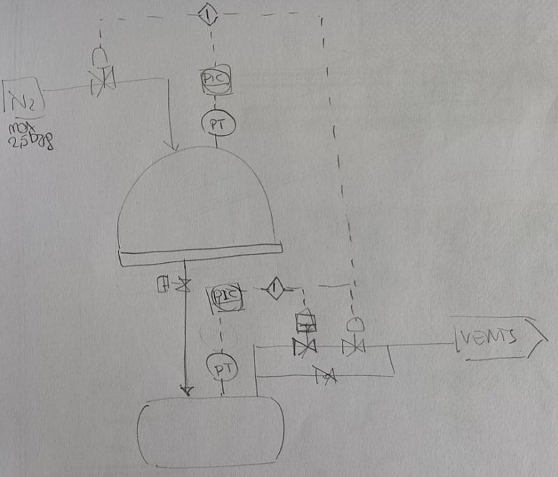
So in my opinion they should have a control loop like this:
- during normal operation the valves on vent line are all open
- when the pressure rises to a set pressure to be defined (say 0.5 barg) all the valves shall be closed (meaning the shut-off valve and control valve on vent line and the control valve on nitrogen inlet line)
- at this point a PID controlled shall be initiated: slowly open the control valve, say 10% open (to be defined by valve vendor) in order to keep pressure downstream not higher than a defined max pressure allowed - say 150 mbarg
- as the pressue upstream the valve decreases, the valve can be opened more and more

Now how do I define the flow rate to be specified for the control valve? Is it correct to consider the max flow rate that can enter the system hence 100 kg/h nitrogen? The client says to consider approx 50% of this value by I do not understand why (they say "as approximation")...
In this new scheme I think that the pressure measure shall be installed upstream the control valve, do you think it is correct?

Immagine_2024-05-23_094638_oubnsf.jpg
 
50kg/hr seems a more reasonable flowrate. Dont know why you have relocated the PIC to to the liquor tank in this recent sketch. Your sketch of 20May is still valid I think. Add the PIC and PCV for N2 flow to the dryer as suggested. Okay, suction pressure to the compressor at the VOC unit would be the right parameter to control with. Your description appears to indicate that there are more than one filter dryer units feeding this VOC booster compressor.
So size this control valve for 50kg/hr rather than 100kg/hr. Get the Cv from the control valve vendor and check for turndown also - Case 2: what Cv will be with flow of 50kg/hr , 250kPag upstream / xx kPag at VOC end. Cv turndown limit is about 30:1.
I would propose this 20May sketch (with mods as suggested), as the basis for discussion and approval from your client. And also the sizing basis for both control valves and turndown calcs.
 
The approximation is probably a reasonable number to use as the gas flow goes through a crack in the cake. Even if its double the valve should cope.

All you need to do is control on downstream pressure to some figure which limits pressure at the VOC cryo unit and not shut or close anything.

EDIT - I agree with George.

Remember - More details = better answers
Also: If you get a response it's polite to respond to it.
 
Thanks everyone!

@ georgeverghese

I located the PIC on the liquor tank because I need to know the pressure upstream the valve to know how to regulate in order to keep the pressure downstream with valve DP. But it is also true that I have a pressure transmitter in the filter so the pressure is the same if they do not close the drain valve.

"Your description appears to indicate that there are more than one filter dryer units feeding this VOC booster compressor."
Yes the VOC unit treats the process vents from the entire site (dryers, reactors, etc... it is a very large chemical plant). This is why it looks unlikely to me that one single vent can affect the cryo unit in terms of flow rate. But I have no data about this VOC unit.
 
You are not controlling on upstream pressure ( the pressure in liquor tank) and whilst that information is useful, it is not needed to control the valve position - all you need is vent line pressure.

You're not maintaining a fixed DP cross the valve, you're stopping the vent line from operating at a higher pressure than the d/s equipment can handle.

Remember - More details = better answers
Also: If you get a response it's polite to respond to it.
 
Hi,
"Yes the VOC unit treats the process vents from the entire site (dryers, reactors, etc... it is a very large chemical plant). This is why it looks unlikely to me that one single vent can affect the cryo unit in terms of flow rate "

I don't understand what your client is asking you, you should get access to all the data related to the VOC treatment, including the capacity of the unit. I cannot believe that 100kg/h of N2 can affect the VOC treatment in use for a full plant with reactors, dryers. This is ridiculous.
I'm pretty sure your client has a map with each individual equipment, including flow rate and VOC content of each stream feeding the cryo unit. I believe your client is reporting to authorities about VOC treatment, this means data are available.

BTW, what is the action plan if the VOC unit is down? Plant shut down!

Good luck.
Pierre


@ LittleInch

Yes you are right, I was thining that the valve is correcting the % opening based on the pressure upstream but this is a consequence of the set pressure downstream. I will correclty install the PT downstream.


@ pierreick

"I cannot believe that 100kg/h of N2 can affect the VOC treatment in use for a full plant with reactors, dryers. This is ridiculous."
That is excactly my thought.

"I'm pretty sure your client has a map with each individual equipment, including flow rate and VOC content of each stream feeding the cryo unit. I believe your client is reporting to authorities about VOC treatment, this means data are available."
My understanding is that they lack documentation or the people cannot find them in their archive. I also asked for updated ATEX classification reports and calcs and they say that do not have anything like that. Which is impossible since they have updated ATEX maps... My feeling is that they have no "time to lose" to retrieve data to solve a problem that clearly is not such a big deal.
 
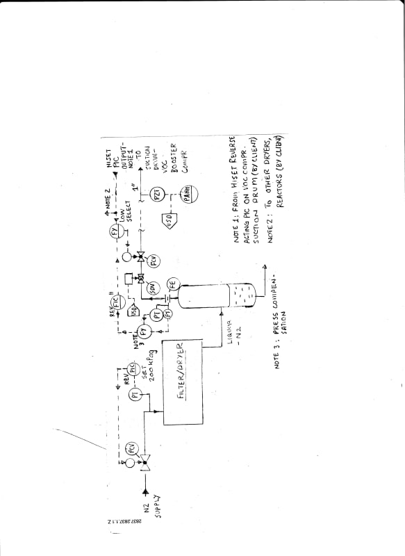
Here is what I think is a better scheme - flow control with pressure override. Flow control is better since it is more responsive to pressure spikes from source filter dryer. So you set the FIC for a constant (50 + estimated VOC mass rate) kg/hr. The rest is obvious from the sketch. The client ought to provide the hiset PIC output signal generated from his VOC compressor. This signal to be used for all other feed sources arriving at this suction drum also.

24may2024filterdryer01ETips.jpeg_laoazc.jpg
 
Thank you georgeverghese!

Is it a flow orifice that you have installed on the vent line (FE)? For what do you size it?
 
From what we know so far, flow would be 50kg/hr + saturation VOC content at VOC recovery compressor suction pressure and temp. Use a dp of 25mbar to start with and see if this works. Since this is a 1inch line, this may have to be an integral orifice assembly - talk to instrumentation folks for details. Instrumentation folks may have alternate choices to the flow orifice element also. Pls note the pressure compensation logic at DCS for density correction to flow measurement.
 
If you are going for this flow control option, would suggest sizing a vapor/liquid separator for this liquor tank / pressure surge drum. See GPSA for sizing guidelines. Use a vane type demister pack at the vapor exit so that liquids entrainment in the vapor stream to the FE is minimised. A vane pack may be preferable to a wiremesh demister in case some of this filter cake solids get caught in the demister; a vane pack can be cleaned up and reinstalled. An access top flange or a manhole on the vessel side then required for access to demount the demister pack.
 
Status
Not open for further replies.

Part and Inventory Search

Sponsor