Continue to Site

Eng-Tips is the largest engineering community on the Internet

Intelligent Work Forums for Engineering Professionals

  • Congratulations Danlap on being selected by the Eng-Tips community for having the most helpful posts in the forums last week. Way to Go!

Pressure in vacuum line 1

Javier Sanchez

Mechanical
Feb 12, 2025
5
Dear all,

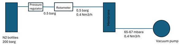
I need to design a system as depicted in the attached image, where I need to feed a fix flow of nitrogen to one membrane under partial vacuum conditions. The setup considers a nitrogen source from bottles and a vacuum pump at the end of the line. The idea is to use a pressure regulator and a flow meter, to feed nitrogen at 0.5 bar and 0.4 Nm3/h, and that the vacuum pump can decrease the pressure in the membranes further to 65 mbar(a). I would like to know how to calculate the pressure profile along the line, from the pressure regulotor to the pump, to know the pressure at which the membrane would be working. Do you know any suitable formula for such setup that can consider pressure losses and the curve of the pump? Thanks in advance!
 

Attachments

  • Setup scheme.jpg
    Setup scheme.jpg
    96.1 KB · Views: 30
Replies continue below

Recommended for you

I did not know the up-down button existed and could have activated it unknowingly on multiple occasion since I use my thumb on the right side of the page to scroll up-down.
 
@Javier Sanchez - You can use a similar technique to the way you would match the curves for a centrifugal pump system. The difference is that you would use the pressure at the *suction* of the vacuum pump.

The upstream gas pressure is fixed by your pressure regulator. The downstream pressure (at the vacuum pump suction) would depend on the pressure drop through the piping and the membrane, and you can plot this on a curve. Similarly the pump flow capacity varies with the suction pressure - assuming constant delivery pressure to atmosphere. Where these lines cross is your operating point.

It seems to me that posts are not coming through chronologically. Your post #16 shows you posted on Saturday but I only saw it on Monday morning. Maybe I missed it on Saturday, but this is not the first time that posts seem to arrive out of order.
 

pierreick

the document is good and i tried the calculation as
The pipe dia is 1" & pressure drop i assumed is 3" Hg and vacuum need at end of the pump is 65mbar (1.92" Hg) so
as per the document you have shared

P1 = 1.92" Hg V. (65 mbar a) This is required vacuum at the end of the pump.
P2 = 37.17" Hg V (0.5 bar g+ 1 bar atm so = 1.5 bar a ) This is the nitrogen bottle absolute pressure in the line before the membrane.
V1 = 0.235 ACFM (0.5 Nm3/hr) This is the required flow rate of nitrogen to the membrane.
V2 = Required flow rate after the pressure drop before the membrane ?

I substituted the values in P1 V1=P2 V2
V2 = (P1/P2) * V1
So i got 0.607 Nm3/hr vacuum flow rate required for 3" Hg V Pressure drop at 1" line.

i avoided the regulator & rotometer pressure drop values and length of the line.

I think i have done a mistake or some wrong understanding of the concept. can anyone please correct me.
 
Asisraja,
P2 is wrong , 1.5 barA =44.2951 inch HG
Attached another document about compressible fluid flow.
Pierre
 

Attachments

  • CompressibleFluidFlowCalculationMethods-edited.pdf
    1.2 MB · Views: 1
Last edited:
thanks for correction

As 0.4 Nm3/hr is 0.68 ACFM. and as you told 1.5 bar A is 44.2951 inches Hg.

V2= (1.92/41.29) * 0.68
= 0.0316 ACFM. 0.0537 Nm3/hr.

I think i should have read them again and clear the calculation part.
 

Part and Inventory Search

Sponsor