Continue to Site

Eng-Tips is the largest engineering community on the Internet

Intelligent Work Forums for Engineering Professionals

  • Congratulations KootK on being selected by the Eng-Tips community for having the most helpful posts in the forums last week. Way to Go!

Pressure Problems 2

Status
Not open for further replies.

Patassa

Mechanical
Oct 14, 2013
51
I've worked myself into a bit of a loop here.

A question came up from a younger colleague today that at first seemed a bit silly but after running a model I might see his point too. Basically, the question was if my pump discharge piping immediately sizes up say from 2" to 20" and I sized the line for pump discharge pressure, could I over pressure the line from almost all of my velocity energy being converted into static energy?

What's curious is that I ran a model with a 2" discharge, 3 inches long, into a 20" line for 10ft then back to a 2" into a tank. The software is telling me that my pump TDH is 40.38 feet, discharge pressure of 19.43 psig, in the 2" discharge piping I only have 4 psig of static head pressure. This seems to be telling me that a pressure gauge on this short section of discharge piping would only read 4 psig. The static pressure then jumps up to 19 psig in the 20" line. So it seems to be that discharge pressure gauges on pumps can be incredibly misleading in cases such as mine? That the TDH converted into pressure is total developed pressure also, but not necessarily static pressure or what I'll see at the discharge of the pump on a gauge? (Is this correct?)

Though converting the TDH into pressure still gives me the correct design data and I'm in no risk of over pressuring anything downstream, it does seem that my discharge pressure gauge readings need to be read in the context of my piping diameter, as my downstream pressure gauges could actually show an INCREASE in pressure if my diameter were to increase.

Am I understanding this correctly?

 
Replies continue below

Recommended for you

Suggest you need to go back to your text books and study pumps and hydraulics. There is a real danger in relying on software if you dont understand enough to query " " Does this output look right?'
 
How much pressure loss does this program report for the 2inch x 20inch piping reducer ? Does that sound right to you ?
 
So I'm not "relying on software" as this was more of a mental exercise just for fun and any system that I design uses the dead head of a pump at it's largest impeller size for design pressure, so there is no "danger" here.
 
So patronizing aside, do you know the answer Miningman?
 
If your pump is pumping, i.e. fluid is flowing, how do you have static pressure, which is what I always thought to be pressure of the fluid with no flow. So friction losses, i.e. reductions/expansions would have no influence on static pressure.
 

If you properly design your discharge line to handle the pump's TDH in terms of pressure (i.e. TDH converted 100% to pressure head), you will not overpressure in steady-state operation. Regardless of flow velocity, line diameter, "static pressure", etc. Energy is energy.
 
The discharge pressures are not read in the context of velocity.

The total energy in the pipeline is the sum of the static, dynamic and hydrostatic pressures. The static pressure is the pressure as measured moving with the fluid that can be measured with a pressure gauge. The dynamic energy depends on the velocity head and will be relatively small. The hydrostatic pressures is the pressure due to the force of gravity

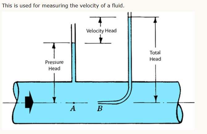
The velocity head can not be measured with a pressure gauge. You need a pitot tube to measure velocity head.

Document127_pddvwn.jpg


However, the hydrostatic pressure will depend on the elevation. If the pipeline is relatively level, the hydrostatic pressure will be constant. If there is significant elevation difference, then there will be differences in pressure due to the elevation. For those applications, the elevation head will have to be added to the static pressure.
 
Patassa,
I agree with most of the above, but there is one point that you need to keep in mind. At relatively low velocities, dynamic pressure is generally (and rightfully) ignored and Bernoulli's relationship whereby

static pressure + dynamic pressure + hydrostatic pressure = constant

is true. At higher velocities, we call "dynamic pressure" "impact pressure" and

static + impact + hydrostatic ≠ constant

and weird things happen inside shock waves.

Dynamic pressure is ½*ρ*v[sup]2[/sup] (in U.S. units you need to throw in a g[sub]c[/sub] to get to lbf from lbm). Do that calculation in the 2-inch and if the dynamic pressure is less than about 3% of the static pressure, then the pressure gauge on the 2-inch is useful. If it is more than 3% of the static pressure then you'll need to move the pressure gauge to the 20-inch because you really cannot draw any conclusions about one from the other.

David Simpson, PE
MuleShoe Engineering

In questions of science, the authority of a thousand is not worth the humble reasoning of a single individual. Galileo Galilei, Italian Physicist
 
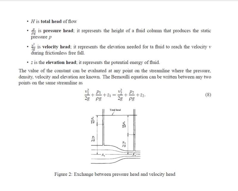
That interpretation of the Bernoulli equation is just plain wrong and a bit of a loop as well. You mention Bernoulli's relationship and then say it is a constant. Bernoulli's equation simply relates the states at two different points in a streamline.

Document128_pmhcqu.jpg


Bernoulli's equation also has some restrictions in its applicability that you fail to note, they are:

• Flow is steady;

• Density is constant (which also means the fluid is incompressible);

• Friction losses are negligible.

• The equation relates the states at two points along a single streamline.

Because of the restrictions, the Bernoulli equation is not used for analyzing shock waves, not because weird things happen.
 
bimr,
You are actually going to start down this tedious road again? Really? OK.

There is nothing in the derivation of Bernoulli's equation that states "constant along a streamline", in fact that addition is quite incorrect and would limit the applicability of the equation to near zero. The streamline demonstration is quite useful in describing why airplanes can fly for example, but as a demonstration, not a proof. The Bernoulli equation applies to bulk properties, not streamline properties.

You seem to be claiming that Bernoulli's big breakthrough is that he defined a relationship between static pressure, dynamic pressure and hydrostatic pressure. It wasn't. The understanding that those terms adding up to total pressure predated him by many years. His breakthrough was defining the list of conditions (much longer than your abbreviated list) whereby the sum of those terms could be considered constant so you could compare one point in a real flow to another point in that same real flow.

I don't have a clue what part of my post was either wrong or circular. I'm not really sure I care.

David Simpson, PE
MuleShoe Engineering

In questions of science, the authority of a thousand is not worth the humble reasoning of a single individual. Galileo Galilei, Italian Physicist
 
This has all been a good rehash of the fundamentals and I appreciate the input. However it's got me thinking about if I've been reading pump curves correctly or not.


If the Y column is total developed head and I convert this into pressure, is this pressure my total pressure (dynamic + static)? If so, why does my total developed head drop off with an increase in flowrate, it would seem that as my flow rate increases my static pressure would go down but be canceled out by an increasing dynamic pressure and my curve should be flat. Obviously this isn't so, but I'm struggling to understand why now.
 
sorry, total dynamic head. I've heard "developed" many times but the textbooks say "dynamic".
 
Static pressure is a characteristic of the system. It is the pressure your system needs when just initiating flow. Some systems increasing in elevation will have no flow until the pump discharge pressure equals the pressure of the column of fluid it is lifting to the highest elevation. That's the static pressure. Dynamic pressure is that pressure needed over and above to sustain any increase in flow above initiation of flow in that system. That which is required for friction caused by any flow in motion (dynamic).

It is "dynamic" head, not developed. Although total developed head must equal the sum of system static plus dynamic friction loss to have sustained flow.
 
Thought that all people that claim to be familiar with hydraulics knew what a "streamline" is. Most hydraulic engineers would also state that the streamline is integral to the derivation of the Bernoulli equation.

Document130_a6gjll.jpg


As you can see from the description above, the energy is constant along the streamline, not just "constant".

 
OMG. Pick a streamline in the flow near the pipe wall at the 9 o'clock position (assume 12 o'clock is top dead center). Then pick another streamline an infinitesimal distance from from the first towards the center of the pipe. Now simplify the equation you included to get it in pressure terms for two streamlines in a single plane.

P[sub]static[/sub] + ½*ρ*v[sub]sl1[/sub][sup]2[/sup]+ρ*g*z = P[sub]static[/sub] + ½*ρ*v[sub]sl2[/sub][sup]2[/sup]+ρ*g*z

Since at a plane, the static pressure is the same across the pipe (the only way that this is not true is if static pressure varies across a pipe cross-section which would invalidate the location of several million pressure sensors) and density is the same at that plane, and since we've chosen a streamline where z[sub]sl1[/sub]=z[sub]sl2[/sub] this equation simplifies to:

v[sub]sl1[/sub][sup]2[/sup] = v[sub]sl2[/sub][sup]2[/sup]

But we know that the velocity of a streamline closer to the center is higher than the velocity closer to the wall (the no-flow boundary requires this result). The only way that Bernoulli works is with bulk (also called average) velocity which is the volume weighted average of every streamline.

Before you come back with another snarky and pointless rejoinder, please ask yourself "when was the last time I was able to isolate a streamline in a flow to measure its velocity?" If the answer is not "never" then you are lying to yourself. If it is "never" then you should be able to see that the streamline model of flow is only useful for allowing humans to visualize idealized flows. We don't really have access to streamline data.

The reference you provided is instructive
J. B. Calvert said:
Bernoulli's Equation applies to steady irrotational flow, and the constant is really a constant throughout the volume of irrotational flow. Nothing is said about streamlines
He goes on to include some information that really requires additional discussion, but the first section is solid.

David Simpson, PE
MuleShoe Engineering

In questions of science, the authority of a thousand is not worth the humble reasoning of a single individual. Galileo Galilei, Italian Physicist
 
I see now that you understand what streamlines are, that is a big improvement. You are also starting to understand that the Bernoulli equation relates to the states at two points along a single streamline as your last post indicated. That is another improvement since your original post remarked about a constant.

Now go back and read the reference again so you understand fully comprehend. The third form (you just looked at the first form in the refence and appeared to stop at that point) is the usual derivative of Bernoulli's equation and includes conservation of energy, includes streamlines and is easily understood by students:

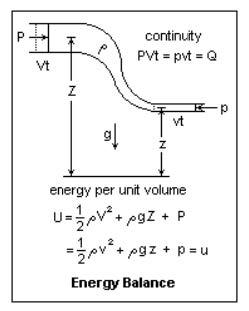
"The third form of Bernoulli's Equation is derived from the conservation of energy. Bernoulli himself took an equivalent approach, although the concept of energy was not well-developed in his time. Energy balance is a favoured method of approach in engineering, and this is the usual derivation of Bernoulli's Equation in elementary work. By the use of energy concepts, the equation can be extended usefully to compressible fluids and thermodynamic processes. In the Figure, an element of fluid is transferred from one point to another in a tube with rigid boundaries. The equation of continuity for an incompressible fluid shows that the same volume of fluid Q disappears at one point and reappears at another. The imaginary pistons move with the speed of the fluid. Capital letters are used for quantities at one point, small letters for the same quantities at the second point. The energies per unit volume, made up of kinetic, potential, and pressure terms are equated. The pressure terms can also be handled as doing work on the element of fluid, which is equivalent. The virtue of this derivation is that can be extended in various directions to give important results, and that it is easily believed by students. The rigid tube can be replaced by a surface generated by streamlines, which can be shrunk down to the neighbourhood of a single streamline, which is just the second form of Bernoulli's Equation, but here derived by energy instead of by dynamics."

Document212888_qexmsi.jpg
 
Yeah, I kind of understand what streamlines are. Something to do with a Masters Degree in Fluid Mechanics.

No comment on how your partially understood concept of this equation would result in two velocities that cannot be equal appearing to be equal in your approach? Didn't think so.

David Simpson, PE
MuleShoe Engineering

In questions of science, the authority of a thousand is not worth the humble reasoning of a single individual. Galileo Galilei, Italian Physicist
 
"Because of the restrictions, the Bernoulli equation is not used for analyzing shock waves, not because weird things happen."

That's not true bimr. Bernoulli's can easily be adapted to analyze liquid shockwave/pressure surge at unsteady flow. However, most are only familiar with the famous steady-state formula, including 98% of textbooks. Bernoulli's is just a mathematical expression for the law of energy conservation, which continues to hold true in shockwave/pressure surge applications, even if your textbook doesn't have a section on it.
 
Hugoniot's fairly complete 1887 exposition of the theory of shock waves was published approximately 150 years after Bernoulli published his paper. Since Bernoulli was no Doc Brown, he did not have access to Hugoniot's work

If you extend the Bernoulli equation by adding some terms, deleting other terms, and changing assumptions as Hugoniot did, the resulting equation may be used to analyze shock waves. However, the equation is substantially different and is no longer known as the Bernoulli equation. The equations to analyze shock waves are known as the Rankine-Hugoniot equations, not the Bernoulli equation.


Status
Not open for further replies.

Part and Inventory Search

Sponsor