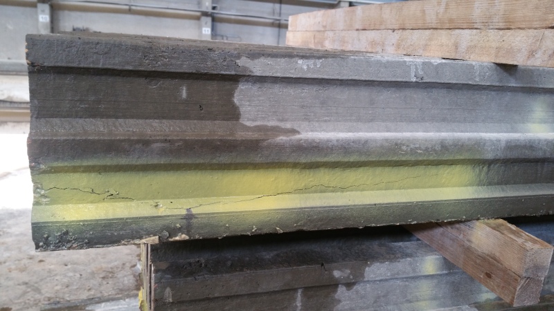
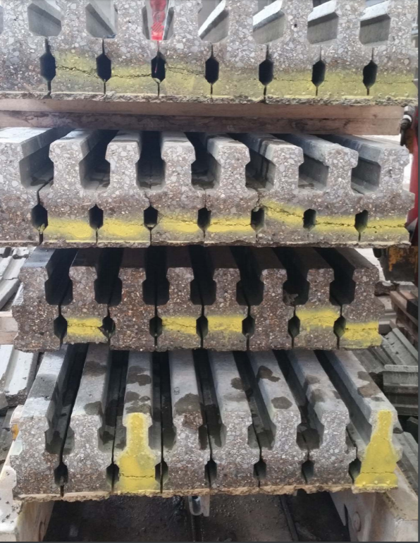
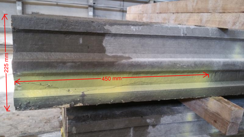
Based upon the 32 beams in the above photo, 21 of them (or 2/3 rds) have horizontal cracking. Not good.
Looks like the product is produced in a long-line bed, using an extrusion process (similar to hollow-core), then cut up into required lengths.
TME's idea of debonding wires or adding transverse rebar may be a major hiccup in your manufacturing productivity - but producing product with such a high rate of cracking is not cost effective either
")
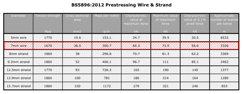
Making a few assumptions and approx calcs:
Assume P
eff is 65% of P
u, so for 5 wires your P
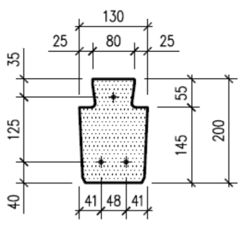
eff is about 225 kN. Eccentricity of prestress is 41.2mm from bottom (57.7mm from CG).
Assuming an equivalent rectangular section of 225mm deep x 85mm wide your I
g is about 80x10
6mm
4, A
g is about 19,200 mm
2
P/A
g is 11.7 MPa!!!
Plug and chug into your classic elastic stress formulae ==> your bottom fiber COMPRESSIVE stress at ends of the member is "theoretically" 28 MPa, and top fiber TENSION stress is more than 9 MPa.
So unless your fci (concrete compressive strength at transfer) is about 40 MPa, you exceed most code-prescribed compression limits of 0.70f'
ci (and tensile limits of 0.5√f'
ci).
Are you steam curing overnight to accelerate your curing and strength gain, and do you bust a cylinder to verify concrete strength PRIOR to transfer?