Eng-Tips is the largest engineering community on the Internet

Intelligent Work Forums for Engineering Professionals

  • Congratulations waross on being selected by the Eng-Tips community for having the most helpful posts in the forums last week. Way to Go!

Prestressing Abutment design

Status
Not open for further replies.

precast123

Structural
Aug 10, 2015
67
BH
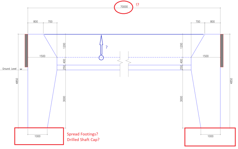
I was designing abutments active end and passive end for prestressing. In the attached pdf 3m below ground part can be designed as short pile? Attached Structural concept will work since the load is very large approx 800 ton..? I am getting 30mm deflection for the abutments when ignoring bottom part below ground. I am analysing in sap2000 using shell element and was thinking to provide spring in abutment portion below ground to reduce deflection assuming this part as rigid pile (short pile). Note : this portion will be excavated and casted not drilled or bored.
 
 https://files.engineering.com/getfile.aspx?folder=4171c5d3-be55-4300-b154-ca94675fb4a1&file=Prestressing_Abutment_Section1.pdf
Replies continue below

Recommended for you

This is definitely a different design than I am used to seeing. It's more like a prestressed bent cap but I guess you guys are using it as an abutment. I've seen other older bridges designed like this but it's an onerous task in grading back to the abutment since these type of abutments can't retain fill. That's why we typically prefer solid wall abutments. Not always, but most of the time. Do you have a lot of utility lines passing through beneath the abutment cap?

As far as your dilemma goes... Do you have spread footings beneath each end of the abutment? Or a drilled shaft cap? Are you currently modeling the base as a pin? You are showing the abutment as 70000 mm long!? Is that correct? If that's the case, your deflection ratio is L/2756. I'd say that's not too bad. What are you concerned about?

If it's excavated and cast, I would certainly not rely on the surrounding soil stiffness. I think that even with good compaction, you won't see that high of spring stiffness to reduce your deflection that significantly. Especially not with 3000mm embedment. You should talk to the Geotech on the job.

PT_Abut_l1vszo.png
 
400 Ton per abutment (A[sub]F[/sub] = 2.5 m[sup]2[/sup])? What is the bearing capacity? How you calculate the 30 mm deflection - lateral deflection assuming cantilever, or settlement? I am not quite sure I understand this set up.
 
I think the OP is describing the design and construction of a new 70m long bed for a precast pretensioning bed for precast prestressed girders, NOT an abutment for a bridge.

OP - I strengthened an existing long pretensioning bed many years ago. To increase capacity for the large horizontally applied prestress forces from the anchorage buttresses we used rows of vertical micropiles on the compression side, and rows of prestressed soil/rock anchors on the tension side, to resist the moment couple of the eccentric prestress bed forces, at both ends of the bed. We monitored displacement during stressing operations after the bed was strengthened and there was negligible horizontal displacement. Maybe worth considering if your ground/geotechnical conditions are suitable.
 
Ingenuity said:
I think the OP is describing the design and construction of a new 70m long bed for a precast pretensioning bed for precast prestressed girders, NOT an abutment for a bridge.

Ha! Well that makes much more sense and would explain his handle (precast123)
 
How did you model the grade beam ? U shaped grade beam is providing passive thrust . Regarding the abutment (which will be excavated and casted) , my suggestion will be , totally cast concrete to pit ,that is, cast the whole concrete to undisturbed soil or, first make a plain concrete pit which is casted against undisturbed soil and construct the RC abutment. The passive soil thrust will develop at exterior surface of the abutment. The horizontal springs could be assumed half value of the vertical.
 
If the indicated load is largely due to prestress force, I am puzzled why you need to extend the abutment 3m below grade. I'll terminate the abutment just below the frost depth, and design the foundation as two spread mass concrete blocks with tie in between.
 
@ingenuity yes true. Its design of bed for casting prestressed girders. My first trial modelling was that for this 70m bed I have assigned springs in Z direction in SAP2000. Applied force on abutments in x direction. No 3m part below ground. The abutments deflected 30mm. I want to keep this deflection close to 0. Hence I introduced 3m part below ground assuming it will behave as short pile (rigid pile) see attached pictures. This assumption is true? As this part will be excavated and casted and then backfilled
Thanks.
 
 https://files.engineering.com/getfile.aspx?folder=310d7b40-8599-48c1-bc96-4c7ceb0fc91f&file=Screenshot_2020-06-06-00-05-15-797_com.google.android.apps.docs.jpg
@ingenuity can you please share the structural concept you mentioned as a sketch. Thanks.
 
You can analyze the abutment as short pile, however, I doubt it will help much. If the 30mm deflection was mainly from the elastic shortening of the prestress bed, I'll try to increase the depth of the bed, and increase compressive strength of the concrete.
 
@retired13 The deflection is mainly due to rotation at bed - abutment interface and soil settlement near abutment . You are right, I will try increasing bed thickeness. Bed is a u shape element. But still soil settlement problem will be still there. That's why I was thinking to restrain rotation using horizontal soil stiffeness.
 
I get it now. You can try to enlarge the foot print of the abutment, either all the way down (3m), or just below frost. It is to minimize vertical settlement, and it will help to resist rotation too.
 
Status
Not open for further replies.

Part and Inventory Search

Sponsor

Back
Top