thedesigner75
Automotive
- Jan 6, 2023
- 16
Hello All,
i can not get this concept: if i have a not so rigid part like an injected molded part...this part has a feature, sort of planar small surface, that is the datum feature that represents the primary datum so how can i qualify this primary datum in term of orientation? i can put a profile tolerance to check that the surface is not so rough, for flatness checking, and this is clear to me, but if this surface is bent? I need to put some orientation tolerance but to what datum as that is the primary datum![[ponder] [ponder] [ponder]](/data/assets/smilies/ponder.gif) ? Thank you for your time
? Thank you for your time
Ciao

i can not get this concept: if i have a not so rigid part like an injected molded part...this part has a feature, sort of planar small surface, that is the datum feature that represents the primary datum so how can i qualify this primary datum in term of orientation? i can put a profile tolerance to check that the surface is not so rough, for flatness checking, and this is clear to me, but if this surface is bent? I need to put some orientation tolerance but to what datum as that is the primary datum
![[ponder] [ponder] [ponder]](/data/assets/smilies/ponder.gif) ? Thank you for your time
? Thank you for your timeCiao


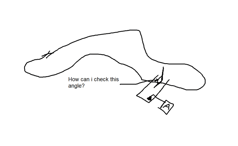
![[neutral] [neutral] [neutral]](/data/assets/smilies/neutral.gif) …i need to sketch up something to be better understood…normally working with flexible plastic parts we have complex parts and small features (like the bad picture i attached above) working as multiple datum features, and these multiple datum features are normally small flat surfaces not coplanar and most of the time not even parallel one to other…so i’m little bit confused how to control them…
…i need to sketch up something to be better understood…normally working with flexible plastic parts we have complex parts and small features (like the bad picture i attached above) working as multiple datum features, and these multiple datum features are normally small flat surfaces not coplanar and most of the time not even parallel one to other…so i’m little bit confused how to control them…![[censored] [censored] [censored]](/data/assets/smilies/censored.gif)