Eng-Tips is the largest engineering community on the Internet

Intelligent Work Forums for Engineering Professionals

Primary Datum on two planes

Status
Not open for further replies.

MPSU

Automotive
Aug 26, 2024
13
0
0
CA
Hey everyone,

I’m back with a bit of confusion and hope you can help me out. I'm still learning GD&T, so apologies if this seems like a basic question.

I received a component drawing where the primary datums are placed on two different surfaces, and the C datum is on a curved surface. My question is: is it acceptable to have primary datums on two separate surfaces?

My suggestion would be to use just A2 and A3, but would that affect the positional tolerance at the B datum in any way?

Thanks in advance!
Untitled_yfnsyz.jpg


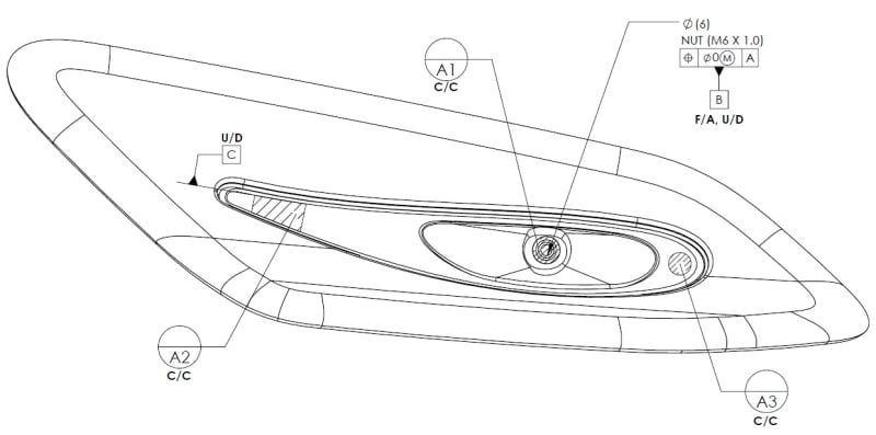
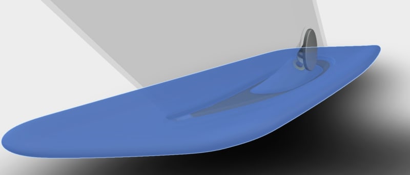
Attached is the drawing and assembly for better understanding.
Untitled1_t5xjys.jpg
 
Replies continue below

Recommended for you

Everything about that dwg is confusing to me. I wouldn't know where to start if I were to make it or inspect it.
Each datum letter should have its own surface.
I don't know what the C/C or F/A, U/D means.

Chris, CSWP
SolidWorks
ctophers home
 
@ctopher: There are just Vehicle co-ordinate system and just shows what datum is restricting what axis i.e. C/C: Cross-car, F/A: Fore-Aft, U/D: Up-Down. For this thread, please ignore these directions for now.
 
Is this ASME Y14.5 GD&T or ISO GPS GS&T?

If it is ASME Y14.5

My question is: is it acceptable to have primary datums on two separate surfaces?

Those are datum target ares so, yes, of course, they can be on separate surfaces. A look at a copy of the standard in the section on datum targets will show examples of that.

The notations, such as C/C and F/A, U/D aren't familiar to me. Edit: OK - you filled that in.

The worst of it is that the datum target areas are small and very nearly co-linear and unlikely to be usable unless they are constrained to be in contact with some defined amount of force.

In addition, there is no locating dimension for the nut used as datum feature B, so position is the incorrect geometric characteristic to use in that feature control frame.
 
@3DDave: It is ASME. Let me use different words, Yes, they can be on different surfaces, but they are on different PLANES.
 
Datum targets are to represent the fixture. The fixture is built so the different target areas are where and oriented as required. They are considered a single datum feature.

The datum targets are defined in the world coordinate system and there can be a plane anywhere in that system that is shown via dimensions from these targets just as the surfaces inspected relative to these targets.


I have no idea what [C] is referring to. There are too many drafted surfaces with rounds ... I don't see it.
 
Hi, MPSU:

The datum targets (A1, A2 and A3) are in-line. They are not robust to be qualified as a primary datum. Position of M6 x 1.0 with maximum material boundary is questionable. For threads, we generally use projected tolerances (P with circle).

Best regards,

Alex
 
Status
Not open for further replies.
Back
Top