Leo44
Mechanical
- Mar 25, 2014
- 6
Hello,
I'm having trouble drawing some wing profile on Abaqus. (note: i don't have access to other software such as Catia or Solidworks, only Abaqus 6.12.2)
I intend to draw a wing profile, with complex curvature and some twist in it.
I wrote a python script to generate different section of the blade
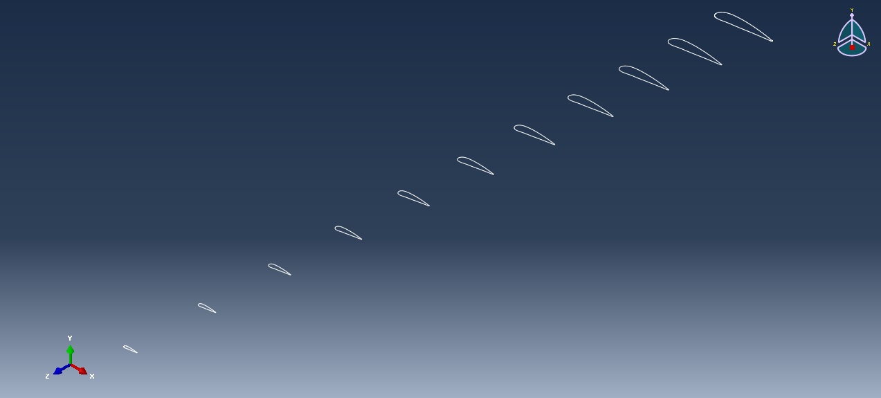
Note that the first and last are actually shells, the inside ones are wires.
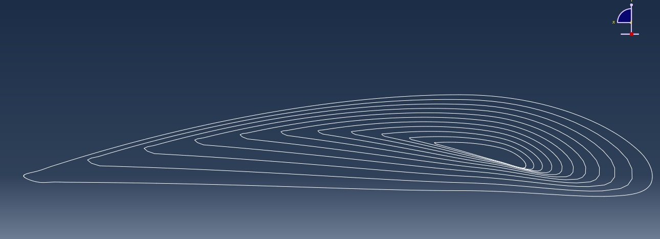
Another view
My plan was to wrap all those profiles with a loft shell. I almost get a perfect result except for some nasty wrinkles due to twisting.
Here is what i get :
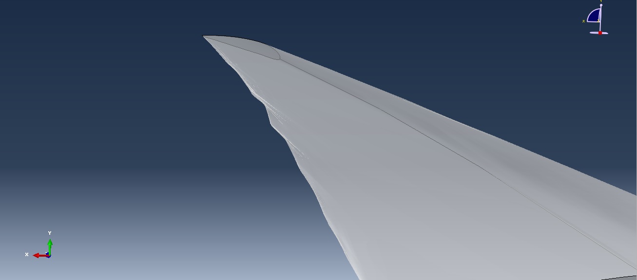
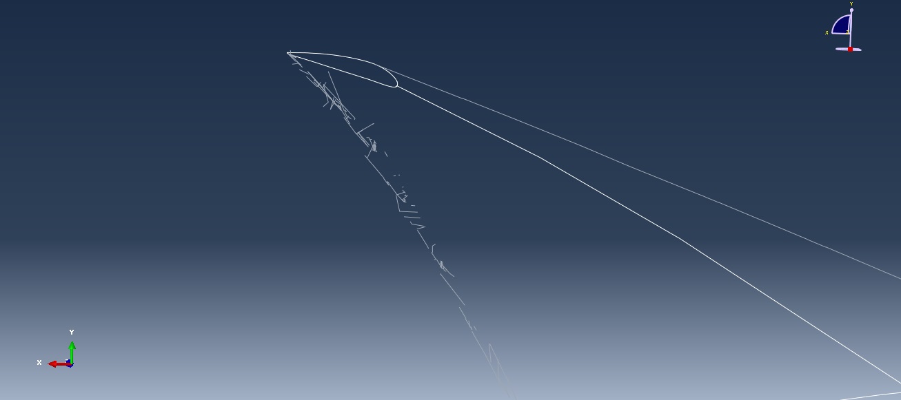
I don't get those wrinkles when i don't twist the wing.
But i really don't know how to get rid of them and obtain a smooth shell.
Should i use another method ? Or is there a more accurate tool than the "Loft" ?
I'm new to abaqus so i might not have seen an obvious solution.
Thanks for the help !![[smile]](/data/assets/smilies/smile.gif "[smile] [smile]")
I'm having trouble drawing some wing profile on Abaqus. (note: i don't have access to other software such as Catia or Solidworks, only Abaqus 6.12.2)
I intend to draw a wing profile, with complex curvature and some twist in it.
I wrote a python script to generate different section of the blade
Note that the first and last are actually shells, the inside ones are wires.
Another view
My plan was to wrap all those profiles with a loft shell. I almost get a perfect result except for some nasty wrinkles due to twisting.
Here is what i get :
I don't get those wrinkles when i don't twist the wing.
But i really don't know how to get rid of them and obtain a smooth shell.
Should i use another method ? Or is there a more accurate tool than the "Loft" ?
I'm new to abaqus so i might not have seen an obvious solution.
Thanks for the help !