Eng-Tips is the largest engineering community on the Internet

Intelligent Work Forums for Engineering Professionals

  • Congratulations waross on being selected by the Tek-Tips community for having the most helpful posts in the forums last week. Way to Go!

Problem in thermosyphon stream 3

Status
Not open for further replies.

Jack Nicholson

Chemical
Oct 20, 2016
119
0
0
IR
Dear all.
HELLO.
I have an is
20211110_092834_o5rbu7.jpg
sue.
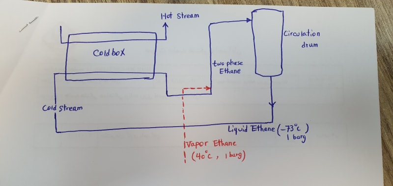
As illustrated on attached picture, liquid ethane is warmed and by thermosyphon mechanism, two phase ethane goes back to circulation drum.

Unfortunately U-type piping right after cold box is done, so it has a negative effect on thermosyphon moving and during decreasing flow of hot stream, thermosyphon flow would be stopped or oscillated.

One solution is to introduce a 1 inch pipe containing vapor ethane to reinforce thermosyphon flow during low heat transfer on cold box. What's your Idea?
 
Replies continue below

Recommended for you

Try easy fixes first, before making changes to the installation.
1) Increase the liquid level in the drum to get more driving force.
2) Shoot for about 15-20% vapor on the outlet of the exchanger. I haven't checked but 40C seems high for ethane at 1 barg pressure - I think you may be over-vaporizing the ethane.
 
I have to assume that there is a vapor line exiting the top of your circulation drum. Otherwise the diagram makes no sense.

I would also not call this a thermo-siphon, which operates due to changing density of the fluid due to temperature, not boiling or gas injection.

I agree with Don. Increase fluid level or increase pressure to avoid boiling in the heat exchanger.
 
Dear Compositepro .
You are right. A vapor line on the top of circulation drum is missed.

I can not understand your statement "it's not thermosyphon.". In this sketch, liquid ethane enter coldbox and two phase ethane (50% liquid, 50% vapor) exit. Isn't this a thermosyphon?

Increasing pressure in order to avoid boiling??? We are supposed to initiate or reinforce the boiling mechanism in coldbox...
 
Outlet pipe just downstream of cold box where downward flow occurs is the problem. Popping up vapor bubbles move upward while liquid moves downward creating counter-current flow. Popped up bubbles will accumulate in cold box creating oscillating unstable flow.

The only way to overcome this phenomenon is to create such conditions when velocity of two-phase vapor-liquid counter-current fluid is higher then velocity of popping up bubbles. These conditions are hard to be achieved as moving force of bubbles is high enough because of Archimedes force caused by difference in density of vaporized and liquid ethane. Bear in mind that the higher velocity of fluid is the lower actual pressure in a pipe segment is and therefore higher vapor fraction and resulting actual volume flowrate and friction losses. Remind that friction losses are compensated by thermosyphon circuit force.

In practice actual pressure in a pipe segment drastically affects vapor fraction in that place and even if you create conditions for enough thermosiphon circuit force (liquid level in the vessel and fluid density in upward pipe segment just upstream of vessel) you will not avoid oscillating - thermosiphon circuit will ooscillate regardless. The effect of measures will be on frequency and power of oscillating only.

U-segment of pipe between of coldbox and vessel is killing thermosiphon and shall be avoided. There is no way to compensate the design this kind of.
 
My first impression is to increased the level in the circulating drum to give up more head to the liquid and force the liquid circulation.. It will be the first solution as operators in these systems. However, the designer has to set enough level separation between the circulation drum and the cold box..

Ask how it works before the problem's began..


Horacio

 
Forced circulation can solve the problem by means of:
- pump is able to provide any pressure rise required to compensate friction losses
- controlled flow (control valve or variable speed drive) is able to compensate flow oscillating

Thermosyphon circulation is the cheapest option but it has limitations - it is selfcontrolled and gravity driven.
 
The obvious solution is to eliminate the U section, but because you have not mentioned it I guess it is not an option.

As you and others have said, the problem is the vapour bubbles collecting in the downleg in the U section. You can get an idea of how bad this is by calculating the Froude Number in the pipe. If the Froude Number is less than 0.31 the vapour will not be carried through the downleg and will build up in this section and decrease the driving force for the thermosyphon. You need to calculate the pipe diameter required to give a Froude Number of at least 0.6 in that section and then work out what the frictional loss will be with the higher velocity (taking the 2-phase flow into account). This will allow you to decide whether there will be any advantage in replacing this section with a smaller diameter pipe.

I would do the same analysis for the horizontal section of the U as I have often seen 2-phase flow cause problems in horizontal piping.

Katmar Software - AioFlo Pipe Hydraulics

"An undefined problem has an infinite number of solutions"
 
@katmar
Can you please share a source where 0.31/0.6 Froud number was originated? I concerned - 0.31 is related to vertical downward pipe or horizontal sloped.
 
You did not give any information on the elevations and cold box cold exchange rates. That would allow to determine the driving forces and size involved.

To my opinion you have a vapor cap in cold box up to the low point of the "U". With nominal cold exchange probably sufficient vapor is generated to have vapor to go into the rising pipe, and due to the difference in weight of the "liquid" column on both sides of the cold box, you get a driving force. With low cold demand there will probably only a gas cap generated, which will stop when nearly all "touched" liquid in the cold box is evaporated. This would include that raising the liquid level in the circulation drum will not help.

I am not sure whether the "U" was a mistake by the designers. Without some restriction in the line back to the circulation drum the velocities can become quite high with the 2 phase stream. Which could lead to less cold transfer in the cold box. They missed however the point with low cold demand.

Your proposed solution with the gas injection, creating a gas lift pump, should work. The supply pressure should be a little bit higher than 1 bar(g) for obvious reasons due to the liquid leg.

An other solution could making a small bypass over the "U", allowing a small flow of the gas cap to go into the rising pipe to enforce the thermosiphon to work also at low cold demand.
 
@shvet - The most comprehensive document I have found is the one by Gilles Corcos.

The value of 0.31 is the limit below which effectively none of the vapour is entrained downwards with the liquid. A value of 1.0 is generally regarded as sufficient to guarantee that a siphon will form rapidly. As the Froude Number increases from 0.31 to 1.0 progressively more vapour will be entrained. The value of 0.64 is often quoted as an overall average for pipelines.

In this case with a vertical downflow section it would be safer to use a value above 0.6 but the higher velocity and therefore pressure drop would be a constraint. We do not have flowrates or pipe dimensions, so I have no idea what the best compromise will be.

Katmar Software - AioFlo Pipe Hydraulics

"An undefined problem has an infinite number of solutions"
 
I would not call this a thermosyphon in order to maintain the distinction between that and gas-lift. Gas-lift uses rising bubbles to pump a liquid, and can be done using any gas, such as compressed air or nitrogen. Thermosyphon uses natural convection to pump fluid. That is a very big conceptual difference. In this case both principles are involved, but gas lift is a much more powerful force, and both are defeated by a dip in your piping.

If you prevent boiling in the in heat exchanger then the gas lift of the injected ethane vapor will work.

Actually, which way is heat flowing in the heat exchanger, and what is the function of the circulation loop? The only thing I can guess is that this loop is stripping off lower boiling components and is being chilled by your heat exchanger. If that is the case your problem can be solved with a small vapor line from the heat exchanger to the top of the circulation drum (with no dips in it).

Your drawing does not show any liquid or vapor leaving the loop. Nor does it show a liquid level in the tank. All are important.
 
@shvet - My humble apologies. You are absolutely right. The only mention of the Froude Number is in the footnote on page 57. It is a while since I used this book and I had forgotten that Corcos used a different way of expressing his equations.

I have attached my hand written notes that I had made in the book for converting between the systems - again my apologies for the untidiness.

I still believe that the Corcos book is the best source of information on the subject, but it takes a bit of translation.

You probably know of other non-English sources and I would appreciate your comments on which sources you have you found best for this data.
Convert_To_Froude_Format_rffqd3.gif


Katmar Software - AioFlo Pipe Hydraulics

"An undefined problem has an infinite number of solutions"
 
Status
Not open for further replies.
Back
Top