AF2023
Mechanical
- Dec 14, 2022
- 3
Hi everyone,
I'm assembling some parts in SolidWorks. I added some screws for the tapped holes on the pictures attached to this post.
I can't understand why there is a material conflit between the screw and the tapped hole in the case of tapping from the bottom edge of the chamfer (here is a section view):
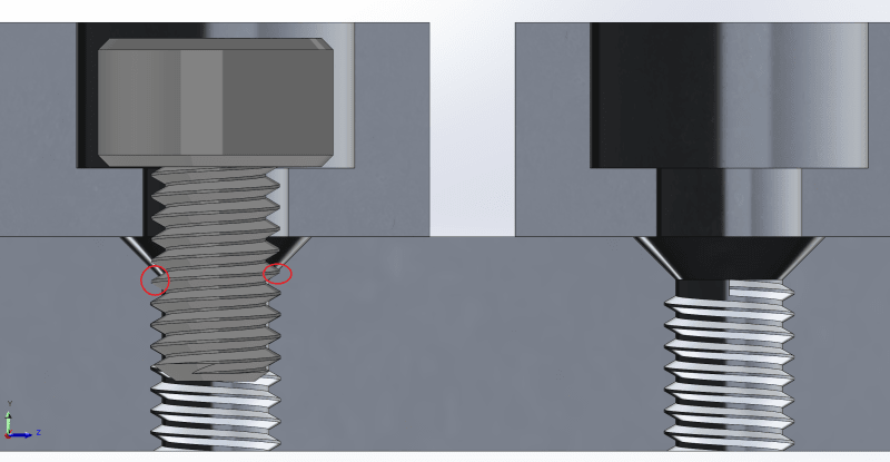
And here is the corresponding top view.
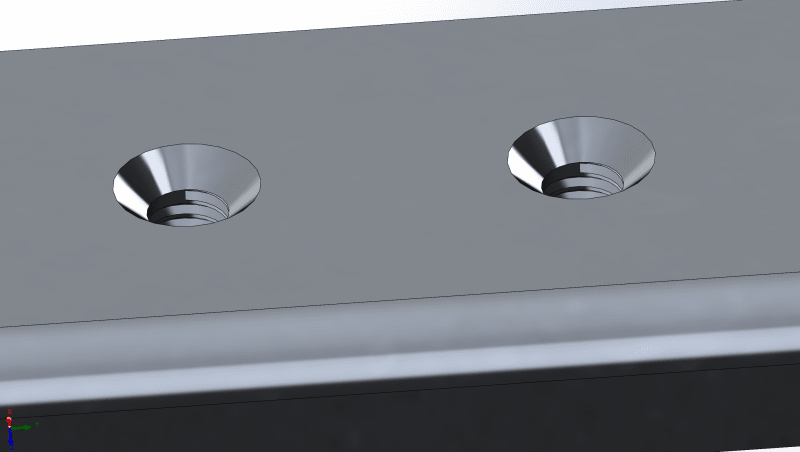
but the problem doesn't occur when the tapping is shifted beyond the bottom edge of the chamfer (thus in that case the tapping goes beyond both sides of the hole):
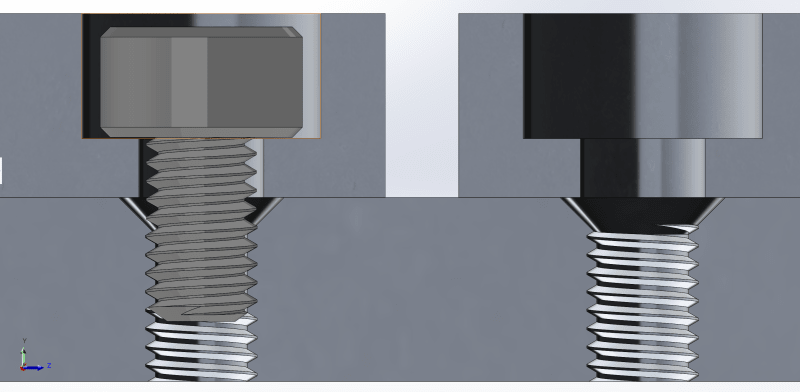
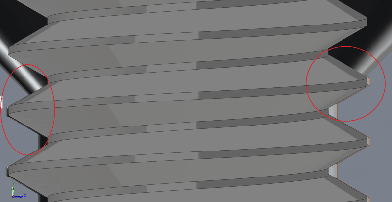
See, there is room now for the first threads:
Again, the corresponding top view:
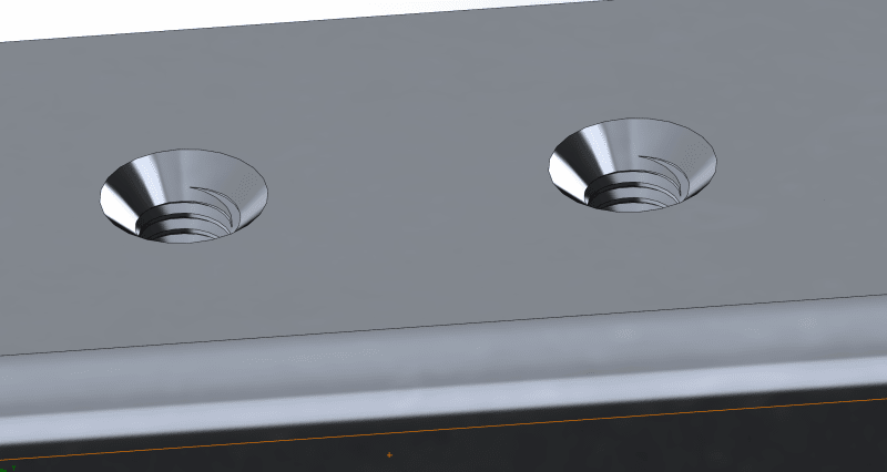
Obviously, that's not what you would except to see when you have a chamfer on a hole. I mean, the threads shouldn't invade the chamfer's zone right ?
Can you help me understand ?
Thanks in advance !")
I'm assembling some parts in SolidWorks. I added some screws for the tapped holes on the pictures attached to this post.
I can't understand why there is a material conflit between the screw and the tapped hole in the case of tapping from the bottom edge of the chamfer (here is a section view):
And here is the corresponding top view.
but the problem doesn't occur when the tapping is shifted beyond the bottom edge of the chamfer (thus in that case the tapping goes beyond both sides of the hole):
See, there is room now for the first threads:
Again, the corresponding top view:
Obviously, that's not what you would except to see when you have a chamfer on a hole. I mean, the threads shouldn't invade the chamfer's zone right ?
Can you help me understand ?
Thanks in advance !
![[ponder]](/data/assets/smilies/ponder.gif "[ponder] [ponder]") I know, the guy in the video completly erased the chamfer zone by using a bigger tap size but i also found this article :
I know, the guy in the video completly erased the chamfer zone by using a bigger tap size but i also found this article :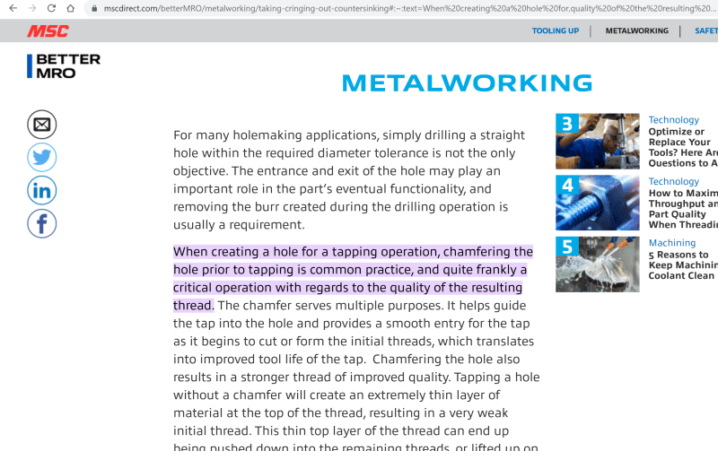
![[pc2]](/data/assets/smilies/pc2.gif "[pc2] [pc2]")