Continue to Site

Eng-Tips is the largest engineering community on the Internet

Intelligent Work Forums for Engineering Professionals

  • Congratulations KootK on being selected by the Eng-Tips community for having the most helpful posts in the forums last week. Way to Go!

Problem with Ordinate dimensions 1

Status
Not open for further replies.

nia573

Mechanical
Dec 9, 2021
6
Using SolidWorks 2014
Ive got a problem using ordinate dimensions & dimensioning to the edge of round tubes.
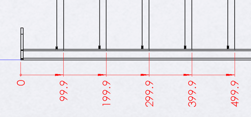
The base line zero is off a flat edge part & I try dimensioning to the left edge of the infill tubes as shown.
(we do it this way as its quicker for the fabricators to measure to the edge rather than guessing where the centre of the tube is)
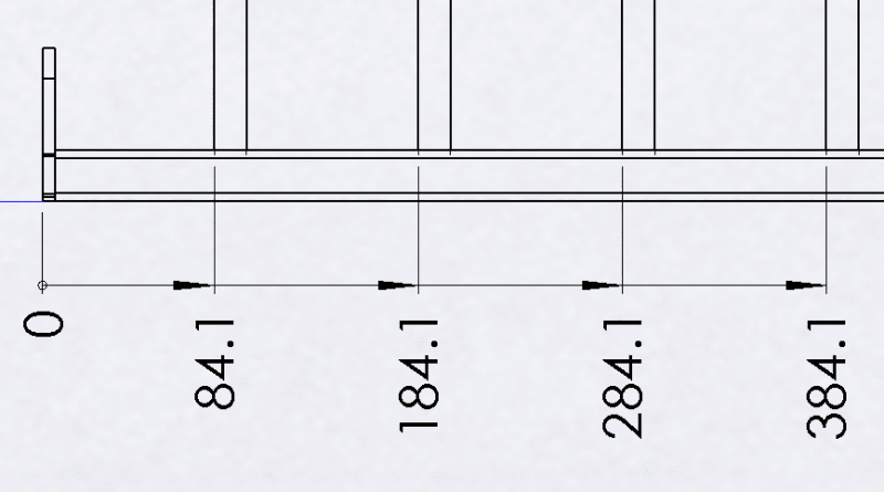
All appears ok but if I do a rebuild the dimensions flip to the incorrect side as shown
Even if I do a convert entities to the left hand side of the tube & ordinate dimension to that, after a rebuild it also flips to the wrong side

In the end I added a sketch point coincident to the left edge of the tube & took my ordinates to that.
Yesterday that worked fine even after rebuilding, but today that too is flipping to the wrong side!
Im getting frustrated & cant see where Im going wrong or what else I could try
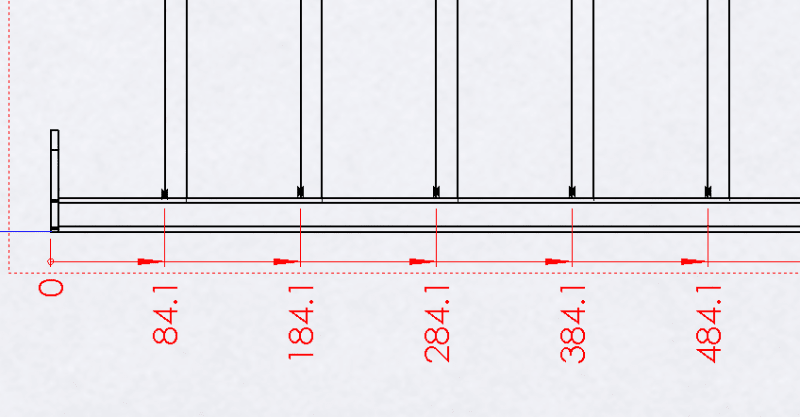
1_Ordinate_dims_before_rebuild_dlcfpb.png
2_Ordinate_dims_after_rebuild_heqvgg.png
3_Ordinate_dims_Converted_entities_on_LH_side_of_tube_dyioz7.png
4_Ordinate_dims_Converted_entities_on_LH_side_of_tube_after_rebuild_slskkw.png
 
Replies continue below

Recommended for you

Just rotate the tubes 180 deg (just kidding).
Looking at the assy, how do they know which end to start from? Assuming it's symmetric?
Dim to the edges should work. In the model maybe mate the tubes so they can't rotate. If they do, the dim's in the dwg can change.
Also, dim to the center of the tubes would probably be easier to measure. Dim to the edge, you have OD tolerances to think about.


ctopher, CSWP
SolidWorks '19
ctophers home
SolidWorks Legion
 
nia573,

My first theory about your problem is that your tubes are following ctopher's instructions, even if you are not.

Are you using SolidWork's weldment feature? Is your section sketch completely defined?

--
JHG
 
It's an assembly at the moment (tube is a part & normally patterned ) not a weldment feature & it's fully defined

The assembly is symmetrical (up to now)
Sometimes it's just a couple of the ordinate dimensions that flip to the incorrect side

Boss wants the dimensions like this as he thinks it's easier for the fabricators to check 🤨

 
nia573,

You really should be using SolidWorks' weldment feature for this. It is powerful, and it is the solution to your other post.

When your dimensions flip, do the numbers increase, or are the tubes moving? When you pick a side of your tube, Solidworks will attach the dimension to that side.

Is the section sketch of your tube fully constrained?

--
JHG
 
Ok thanks for the advice

Currently the upper & lower sections are rectangular 50 x 25 section parts with laser cut holes through one face for the correct vertical infill spacing

The parts are extruded from fully constrained sketches from our company library

When using the ordinate dimensions they appear correct then after rebuild they flip to the other side (increasing by the tube diameter)
 
nia573,

That tells me your parametric modelling does not work the way you think it does.

I suggest you localise the positioning of your tube and see if your dimensions work. You can re-apply external parameters later.

--
JHG
 
My $0.02...

I always base oridinate dimensions from sketched lines (not points) attached to the drawing view. Much easier to reposition or reorient if model references get lost.

Also make sure your drawing view is in projected mode, not 3D mode.
 
I was gonna try and reproduce your problem, and then noticed that you were using SWX 2014.

I've tried in 2019 and can't, including by rotating the seed of the pattern.

Hmm.

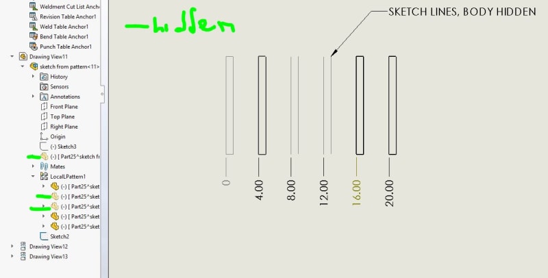
How bout you make a sketch in the assembly and then show it in the drawing. This could be the seed for a sketch based pattern, or a child of the pattern, depending on how you do it.

Try putting a plane thru the CL of the pattern, so you will have two intersections of each round face, and one will be your left side of the post that you want to dimension.

On that plane
New sketch > intersection curve > select all the post bodies

This will make you a sketch that you can show and dimension to in the dwg.

If your boss pays for subscription, this might persuade them to upgrade. What OS are you running on?

 
Or

same sketch, but in the part. then the sketch gets patterned with the part. Make sure to fully constrain the pattern seed so it doesn't spin. Show the sketches, make sure sketches are visible in the dwg, and try again.

 
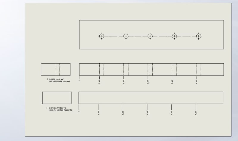
Or try this:

Hide the pattern seed and pattern in the view that you are dimensioning.

Show hidden lines in the view (or just the hole pattern)
Dimension to the hidden line of the hole.

Change view to hidden lines removed (or hide hidden lines for the hole pattern)

Change precision and rounding on the dimension as needed, say if the hole is significantly larger than the post.

Show the post seed and pattern again.

DIMENSIONS_W_HIDDEN_REMOVED_attpol.jpg
 
Status
Not open for further replies.

Part and Inventory Search

Sponsor