Eng-Tips is the largest engineering community on the Internet

Intelligent Work Forums for Engineering Professionals

  • Congratulations waross on being selected by the Tek-Tips community for having the most helpful posts in the forums last week. Way to Go!

Problems with Patran 1

Status
Not open for further replies.

Serrat96

Automotive
May 12, 2020
2
0
0
ES
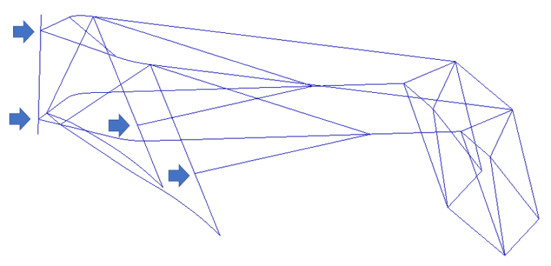
Hello guys, I'm a spanish student and I have a FEA subject on my automotive engineering degree. We have to make a quick PATRAN final project. Not very elaborated, but it has to be ok and show the results after calculating. I designed a Moto 3 chassis in Catia V5R21 (not very good but I did it in 10 minutes) only with lines.

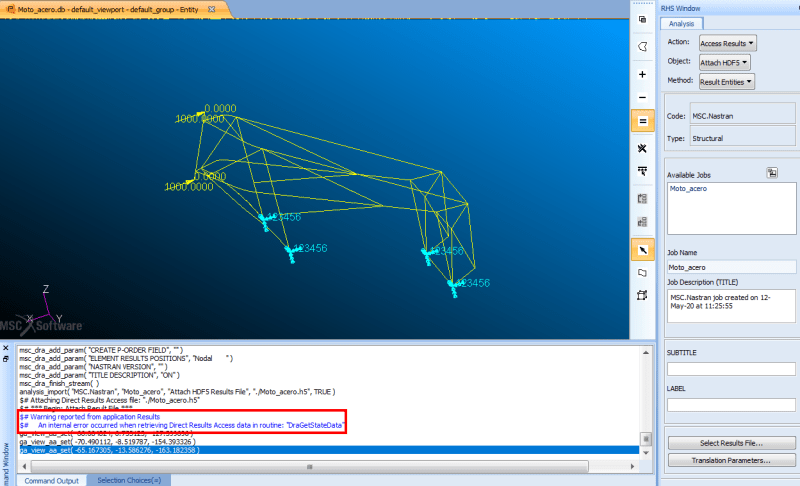
My idea was to import my lines geometry from catia in .stp format and once in Patran give it 1D Beam properties. I did it, put the load cases and fix points, meshed etc but after calculating and trying to import the HDF5 data to see the results I always get the same error message. Someone knows which mistakes am I making?

I attach too the .db file in case someone would like to inspect it in detail.

Thank you all very much in advance.

a_ciakib.png


Replies continue below

Recommended for you

The HDF5 is not being attached because it does not contain any results information. This is because your model will not run in linear statics in the current configuration. The elements at the locations indicated below are not connected. The head-stock of the frame is not connected at all to the frame (the 2 left most arrows), and the two triangulations are only connected at one end.

Screen_Shot_05-13-20_at_08.09_PM_ji8fek.png


You will see which parts of the structure are unconnected if you run a normal modes analysis and request at least 10 modes.

DG
 
Thank you very much for your help! Do you know how can I do to connect those points? I tried in Catia but it is impossible...
 
You have 2 possibilities:
1. Modify the geometry in Patran.
The geometry was imported as curves. Curves connect to points. Make sure the curves for the headstock connect to the same points that the frame connects to otherwise when you mesh, the mesh will be unconnected. Same remark for the triangulation curves. Once connected, then remesh.

2. Modify the mesh
Use Finite Elements, Modify, Node, Move to move the 2 nodes of the headstock closest to the frame junction so that the node of the headstock is coincident with the node of the frame. Do the same thing for the triangulations. Once all is in the right place, use the Finite Elements, Equivalence, All capability to "merge" or "equivalence" nodes that exist at the same geometric location. This will connect the mesh and delete the now unused duplicate nodes.

As a last remark, I notice you applied the fixed node boundary condition to the geometry (points). Be careful here. If the curve/point is not "associated" to the nodes, the boundary condition will not be applied. It seems attractive to use geometry to define the boundary conditions, but I _always_ use the FE (nodes/elements) to define BC's.

DG

 
Status
Not open for further replies.
Back
Top