Eng-Tips is the largest engineering community on the Internet

Intelligent Work Forums for Engineering Professionals

Process Column falls off of Transporter 2

Status
Not open for further replies.

StressGuy

Mechanical
Apr 4, 2002
476
0
0
US
I don't have more detail yet other than the pictures in the article:

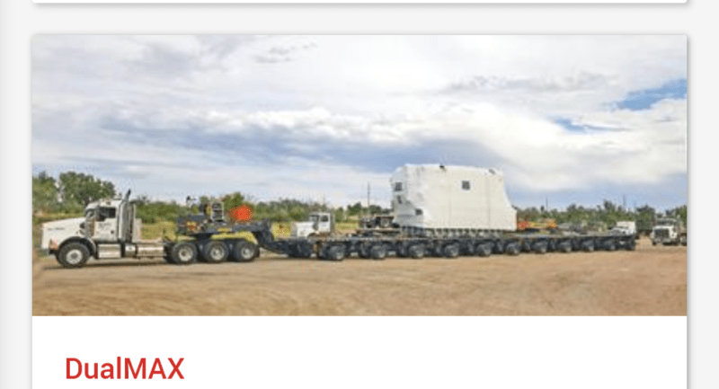
350,000 LB Process Column falls off of Transporter

I was really surprised to see this, especially on a straight road as this heavy haul transport is a pretty mature business. The last time I saw anything related to a transporter losing a load, it was trying to make a turn.

There are some comments I've seen from supposed witnesses that the car that got crushed raced around the escort vehicles trying to pass the transporter and ended up colliding with.

Edward L. Klein
Pipe Stress Engineer
Houston, Texas

"All the world is a Spring"

All opinions expressed here are my own and not my company's.
 
Replies continue below

Recommended for you

The fourth photo in that gallery - the one with all the rescuers working underneath the column, with it (maybe) stabilised by a row of jacks, earth anchors and chains - just makes my hair stand on end.

A.
 
See
it looks like a palletized cradle that the column is attached to with a large amount of chain (4 chains in place, one has come loose), but the pallet wasn't attached to anything - no sign of breakage or bending. It has some kind of king-pin mount underneath, I suppose to allow the trailer to turn without bending the column, though unless there are only two of them there will be too much constraint anyway.

That this much column could come loose without toppling the trailer is concerning.

The suspension looks like Scheuerle units, so this was the aft end. It looks like there was a push vehicle by the presence of the tow bar (in other photos)
 
It wouldn't let me connect tot he first link but this one
has the other end.

Very difficult to see why this should have happened. Everything looks straight unless one of the tow trucks swerved and set off a rocking motion.

The supports look like separate temporary ones and most of the locking force is gravity and friction by the look of it. There really isn't much holding it down.

Remember - More details = better answers
Also: If you get a response it's polite to respond to it.
 
Look at the blocking. This structure is very long but is only sitting on blocks in 2 or 3 locations. The trailer appears to be built up of 2 axle segments. That means all of the weigh may have been on as few as 8 axles. In this case it may have exceeded the road's weight limits.
 
Yes, it looks like every version of the story including my OP is using the same four images from the Temple Fire & Rescue posting. Those four images are all we have to go at this point.

Edward L. Klein
Pipe Stress Engineer
Houston, Texas

"All the world is a Spring"

All opinions expressed here are my own and not my company's.
 
The suspensions are hydraulic load distribution suspensions. All wheels of any trailer segment will have nearly identical loads. This load distribution capacity allows it to cross bridges without overloading them. This is the system used on the M1000 HETS trailer for the M1 tank and the Tunner 60k transporter, both of which I worked on. **


In the case of the M1000 HETS trailer, there is another cylinder that shares the load via the gooseneck to move weight to the tractor.

Notice that the trailer segments cannot pivot relative to one another. I believe there is a bridge structure that carries the bending load across that joint.

Also note that each suspension is steerable, allowing even long trailers to go around corners with the trailer group remaining straight.

** Typically the load is centered right-to-left, which is good. To keep the trailer from rolling over all the right hand suspension cylinders are joined on any segment and all the left hand ones are joined. It looks like the combined multiple sub-units into larger segment.
 
The trailer would have to be very rigid in order to distribute two block loads across its entire length. I guess that a properly strapped column would add to the rigidity of the system.
 
It doesn't need to be very rigid. That's what the linked hydraulic cylinders do. They are all plumbed together to form a raft of hydraulic suspensions. As long as the sag where the load is applied doesn't bottom out the cylinders, it could have a noticeable bend; they don't normally do that, but rigidity of the structure isn't key to distributing the load.
 
Were they overtaking the other vehicle or visa versa?
A little gust of wind, some sway and the two vehicles come together.
But how then entire rig didn't roll is beyond me.
I wonder who made the column?

= = = = = = = = = = = = = = = = = = = =
P.E. Metallurgy, consulting work welcomed
 
Ah - I didn't recognize it before - this image shows the pickup truck under the column, the one with the end of the column base opening. Look to the right of the orange vested fireman.


There is a large jog in the platform, as if the rear unit(s) steered out from underneath the column. All the wheels should line up, especially when the platform is heading basically straight - see the video link I posted just above.
 
Yes, the other thing I'm noticing is that right in the middle of that picture, pretty much right in front of the guy in the vest, is the support cradle that the near end of the column was sitting on. We're looking at the bottom of it in this picture.

It's hard to conceive of the combination of motions that lead to the saddle sliding off the edge of the carrier. Once it did, it looks like it embedded itself in the road and then flipped away from us as the column rolled out of it.

Edward L. Klein
Pipe Stress Engineer
Houston, Texas

"All the world is a Spring"

All opinions expressed here are my own and not my company's.
 
I got this from the Faymonville website.

Screenshot_20240502-191257_fvdofw.png


How is any of the weight transferred all of the way out to the wheels on the right? Surely the modular dollies are not rigid enough.
 
Status
Not open for further replies.
Back
Top