Continue to Site

Eng-Tips is the largest engineering community on the Internet

Intelligent Work Forums for Engineering Professionals

  • Congratulations SSS148 on being selected by the Eng-Tips community for having the most helpful posts in the forums last week. Way to Go!

Product Misalignment at Conveyor Transition

ColdKurd

Mechanical
Apr 16, 2025
3
Hi fellow engineers


I’m experiencing an issue with the transition between two conveyor belts — from the belt coming out of the cooler to the next one.

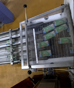
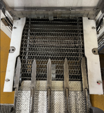
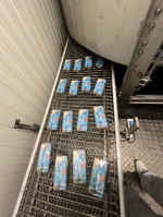
Occasionally, the product comes out misaligned on the belt, possibly due to vibrations from the spiral tower cooler. The current guiding pins, as shown in the attached image, are not always sufficient to guide the product through. As I mentioned, the products sometimes exit at an angle, hit the tips of the pins, and cause a buildup on the belt, which leads to a line stop. I've also attached a video showing when this happens.

Is there a smarter or more flexible solution that can better handle products coming out at an wrong angle? I'm thinking perhaps an alternative to the pins — maybe some kind of rollers or wheels on the tips? I’m open to suggestions and ideas.
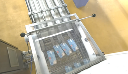
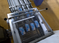
Skærmbillede 2024-10-03 094145.png1744791166037.png
1744791319444.png1744791432422.png
View attachment vlc-record-2025-04-15-14h37m31s-GX010199[1].MP4-.mp4
 

Attachments

  • vlc-record-2025-04-15-14h37m31s-GX010199[1].MP4-.mp4
    8.9 MB
Replies continue below

Recommended for you

Did it ever work?

Has something changed, like the speed of the product?
Is the product guaranteed to be semi-aligned before it gets to this section?
 
Did it ever work?

Has something changed, like the speed of the product?
Is the product guaranteed to be semi-aligned before it gets to this section?

It has never worked particularly well, even though the cooler speed settings should be optimal.
At the infeed, I’ve installed guides to ensure the product enters the cooler in a straight line. However, since the product passes through two large spirals inside the cooler and the belt has limited friction, the product can shift if there are small jolts in the belt.

That’s why I’m looking for a smarter solution to improve the current guiding pins.
 
It looks like a friction issue. The wire belts are not grabbing the packaging. Can you use a silicone belt? why is the transition strip off of belt 1 onto belt 2 so wide (because of sprocket diameters) - if you changed to a silicone belt, you could use a nose bar. Is the speed increasing slightly at each conveyor transfer - if not you are pushing the package onto the angled wire and causing it to skew. Whose wire belt is installed on the conveyor? Call the belt supplier and ask these questions and request a review of your selections.


conveyorbelt02.jpg
 
I would look at making V-guides that cause the bars to fall into the proper horizontal spacing or get high tech and use cameras and servo arms to guide them.

Of the latter, I really enjoy the tomato sorter that is handling a thousand tomatoes a minute across a wide belt and slapping the green ones in mid-air out of the stream.
(time 50 seconds)

Anyway, slide them off the belt onto a formed sheet that has 3 peaks, one in the center to get the center two set to the right and left and two outside peak to align the left and right most bars against the outside limits.

As long as the CG of each bar is in the correct side of the peak it should go the right way. At the bottom of the slide they can flatten out again to line up with the dividers. If they need help some powered wheels or use 4 twisted slick belts to carry them if there cannot be any drop.
 
Maybe if the fingers were more 3-dimensional. If they had a triangular cross-section then packages would be more likely to slide back down, onto the belt, instead of getting stuck on top of the fingers.

A rounded tip, instead of pointy, might also help.
 
That whole set up is super dodgy.

What happens up stream of the bit we can see?
How are they placed in position on the conveyor?

Only thing I can see is to have a set of guides extend through the plastic fronds all the way to upstream of where the packets get placed onto the conveyor. So a bit like the bump guards you see on 10 pin bowling alleys for the kids.

Or some vertical pins on the belt, but that looks very time consuming to build.
 
Thank you for all your suggestions. Replacing the belt is not an option, as it is over 100 meters (328 feet) long. That would be a very costly investment, which is not feasible at the moment. Installing guiding pins all the way through to where the product is placed isn't possible either, as the line runs through two spiral towers, each around 5–6 meters (16–20 feet) tall.

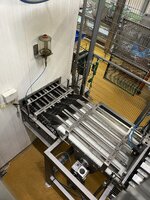
I've attached some pictures from the beginning of the line, where I built a new guide unit that ensures the product enters the cooler in a perfectly straight line. The issue, as I’ve mentioned, is that inside the cooler itself, there are small movements or jolts in the belt — for example during start/stop sequences — which cause the product to shift. The low friction between the product and the mesh belt is also not ideal, as some of you have already pointed out. That’s why I’m looking for a specific solution at the cooler’s exit — for example, modifying the current guide pins where the products tend to get stuck, as shown in the attached pictures and video.

For those of you who suggested changes to the guiding pins — would it be possible for you to illustrate what you have in mind?


1. Newly built, adjustable guide unit that ensures the product enters the cooler in a perfectly straight line.
Inlet to cooler.JPG


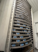
2. Inside the cooler, this is one of the two spiral towers within the cooling unit.
Inside cooler.png

3. This is inside the cooler, just after spiral tower number two, right before the product exits to the guiding pins where the jamming typically occurs
Indside cooler right before outlet.png
 
I'm fascinated by this one.

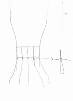
One idea I had, which may seem odd, but in the bit before this splitter, maybe force / guide the tins? gently into a more compact set of four with only say 1mm between them, then knowing they are very close together split them apart with a very sharp edged guide. The tins look to me like they have rounded coreners so knowing eaxactly where the tins will be will allow you to split them apart and guide them into the second set of rollers.

So like this with the tins coming down from the top.
Screenshot 2025-04-25 105648.png
Maybe?

So long as your tins are not at 90 degrees then the risk of jamming is smaller?
 

Part and Inventory Search

Sponsor