Continue to Site

Eng-Tips is the largest engineering community on the Internet

Intelligent Work Forums for Engineering Professionals

  • Congratulations KootK on being selected by the Eng-Tips community for having the most helpful posts in the forums last week. Way to Go!

Profile control and size 2

Status
Not open for further replies.

gabimo

Mechanical
May 2, 2013
124
dwb_-_Copy_-_Copy_sldg5h.jpg


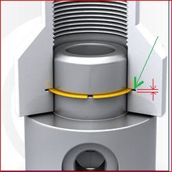
The location of the upper surface of the snap ring (green arrow)is less important than the width of the opening (red arrows).
A profile of surface within .020 back to a datum reference frame is added to green surface and a ± width of the slot within .005 is added for size.

The checker sent this drawing back to engineering as violating 8.2 profile per ASME Y14.5-2009.
"Where profile is used as a refinement of a size tolerance created by toleranced dimensions, the profile tolerance must be contained within the size limits".---meaning profile size (.020) must be smaller than width size (.005).
Profile .020|A|B|C|
width size .100 ± .0025 (per rule#1, green upper snap ring surface should be only flat within .005)

Is the checker correct? Why such a provision (8.2) in 2009 standard? If his interpretation is wrong what exactly is he missing?
 
Replies continue below

Recommended for you

Doesn't that profile tolerance allow the slot to be at an angle to the axis of the part and therefore unable to allow the snap ring to fit both parts at the same time? If it's to one face of the slot it's not a refinement of size.

I'd only put the profile to one face of the slot, add a really small perpendicularity/parallelism tolerance to the width and let size govern the width.
 
3DDave said:
I'd only put the profile to one face of the slot, add a really small perpendicularity/parallelism tolerance to the width and let size govern the width.

3DDave,

How your solution will solve the OP's issue? Why cannot be argued the same way as the OP's solution?
Are you planning to change slot's size just for the sake of not being smaller than the profile tolerance zone (location of the upper face of the slot)?

I am trying to learn something here.

Thank you very much.
 
The OPs solution accepts unusable parts. I cannot guess how you misread my answer. Please advise.
 
3DDave,
Maybe I misread your answer, but could you, please explain a little bit more what "If it's to one face of the slot it's not a refinement of size." means, maybe with an example.

Also, by the same token, how adding perpendicularity / parallelism to the width will solve the issue of 0.020 location for the upper face being bigger than .005 slot width?

Even if you use a composite profile:
prof .020|A|B|C
.002|A|

the problem is still not solved because the location .020 is STILL bigger than .005 slot width

 
The location tolerance allowed by profile being larger than the value allowed to the slot width is not a problem.
 
OP said:
The checker sent this drawing back to engineering as violating 8.2 profile per ASME Y14.5-2009.
"Where profile is used as a refinement of a size tolerance created by toleranced dimensions, the profile tolerance must be contained within the size limits".


3DDave said:
The location tolerance allowed by profile being larger than the value allowed to the slot width is not a problem.

Why those 2 statements (red versus blue) are not in conflict with each other?

 
I agree with 3DDave, profile is not a refinement of size in this case - it provides location control of the groove. Ie: the face may be between (basic_distance + 0.01) and (basic_distance - 0.01) from the specified datum features. It could possibly control form of one side of the slot if it were tighter than the deviation allowed by rule #1 (or if the form tolerance was applied and rule #1 was overridden) but it does not have to be. Without getting into the implications of cones in combination with directly toleranced dimensions and profile, the standard uses 8-17 as an example of where profile is a refinement of size.

As was pointed out though the profile tolerance applied could allow for significant orientation error of the groove. Though of course if the groove is produced on the same operation as the OD of the shaft, say on a lathe, the orientation may inherently be very good it would be wise to add a refinement on the drawing.
 
I agree with chez311. In the snap ring groove example, the profile tolerance is not a refinement of the size tolerance. It does not refine the size or form of the slot.

The statement in 8.2 refers to certain special-case situations where a profile tolerance and a directly toleranced dimension are both present on the same feature. The only examples of this in Y14.5-2009 are Fig. 8-17 and 8-18 (conicity), and also Fig. 8-27. In all of these examples, the profile tolerance refines the form of the feature (controls it more tightly than the size tolerance would). I would say that all of these are troublesome - they all define a tolerance zone relative to an "untrue" profile. ;^)

The checker is off base on this one.

Evan Janeshewski

Axymetrix Quality Engineering Inc.
 
axym said:
The checker is off base on this one.

Looks like I was off base too. Thank you for straighten me out.

Per 2018 debated statement reads:
"When used as a refinement of a size tolerance created by toleranced dimensions, the profile tolerance shall be contained within the size limits


Per 2009 I see no change:
"Where used as a refinement of a size tolerance created by toleranced dimensions, the profile tolerance must be contained within the size limits
 
Yes, the checker is off base on this one.

If the drawing was per Y14.5-2018, there would be one good figure to show him/her to prove this. Fig. 7-41 shows 3 width-type features of size controlled with +/- size dimension, out of which location of two of them is controlled with a profile tolerance of a value larger than the size tolerance (0.5 for profile vs. 0.4 for size). Unfortunately, a similar figure in Y14.5-2009, fig. 4-34, does not show enough details to be able to use it as a proof.
 
Another alternate would be to tolerance the slot location with a position tolerance to the bore and some axial reference and use a perpendicularity tolerance to the bore so the parts all fit together.
 
Status
Not open for further replies.

Part and Inventory Search

Sponsor