Eng-Tips is the largest engineering community on the Internet

Intelligent Work Forums for Engineering Professionals

  • Congratulations waross on being selected by the Eng-Tips community for having the most helpful posts in the forums last week. Way to Go!

Profile of a line application?

Status
Not open for further replies.

njm789

Automotive
Oct 9, 2019
25
US
Has anyone seen a profile of a line tolerance applied to the edge radius of a washer? To me it seems overkill...why not just use a plain old radius dim? Are there any advantages to using a profile of a line like shown below, if so how would it be measured? The B datum is attached to the outer diameter.
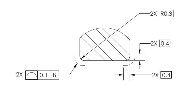
GDT_jarsdc.jpg
 
Replies continue below

Recommended for you

The plain old radius dimension has zero tolerance at the tangencies if the radius is incomplete or goes a bit deep the part should be rejected. In other words, if at some microscopic level the radius is not perfect at the ends then the part is rejected. In this case there is a uniform tolerance for inaccuracy along each entire line.

You need to discuss with the originator of this what they trying to fix/control. I expect that this is not the best solution for a suitable control.
 
njm789,

I agree that the tolerance zones for profile of a line (two arc-shaped boundaries 0.1 apart) would be different than for radius tolerances (crescent shaped zone between two tangent arcs). The crescent-shaped zone is shown on p. 36 of Y14.5-2009.

With the offset phantom lines, the designer may have been trying to indicate a unilateral tolerance zone that would allow a plus-material condition but not a minus-material condition. Or they may have been trying to indicate that the profile tolerance zone extends past the radius and controls part of the flats. It's hard to say, because the drafting is nonstandard.

Evan Janeshewski

Axymetrix Quality Engineering Inc.
 
Status
Not open for further replies.

Part and Inventory Search

Sponsor

Back
Top