huntengine
Automotive
- Jan 28, 2016
- 2
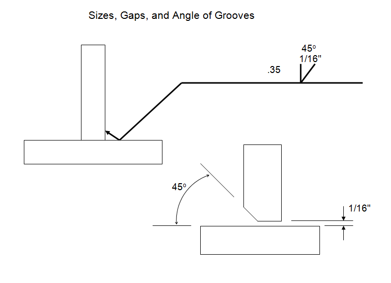
I have an issue trying to figure out how to correctly display the profile to surface callout on my component print. The component mates to another component in the assembly and there is no gap between the two in CAD (I don't have the option to modify the CAD). The two are welded together to make the assembly and I want a gap between the two for the welding process. I want all of the gap tolerance to be applied to the component I'm making this print for and I want between a .5mm and 1.0mm gap. So with the CAD showing no gap I'm not sure if the Unilateral modifier is the correct modifier to use since I'm looking at -0.5 to -1.0 tolerance on this surface.

