Continue to Site

Eng-Tips is the largest engineering community on the Internet

Intelligent Work Forums for Engineering Professionals

  • Congratulations waross on being selected by the Eng-Tips community for having the most helpful posts in the forums last week. Way to Go!

Profile Tolerance in General Note

Status
Not open for further replies.

dragonfire613

Aerospace
Aug 22, 2013
7
We have several drawings that use a combination of two general notes to define a part, as follows:

(1) "THIS DRAWING SHALL BE USED WITH MODEL <CAD MODEL FILENAME> FOR COMPLETE PRODUCT DEFINITION. MODEL FEATURES ARE NOMINAL."

(2) "ALL SURFACES ARE (PROFILE SYMBOL) .060 UNLESS OTHERWISE SPECIFIED."

For this discussion, we will say the drawing itself has no further dimensions or feature controls, so the part is completely driven by the 2 above notes and the cad model.

After years of doing things this way, a new quality inspector is saying that in essence our notes are meaningless without datum references or adding "ALL AROUND OVER" to note 2, and that all parts will inspect as good no matter their geometry. I can say in the past, this was interpreted for a "best fit" using CMM meaning the model and profile tolerance generated a max/min envelope in which the part must fit.

Looking for more input on this. Searching through ASME Y14 seems ambiguous from statements such as 8.2.3 "Where the profile of a tolerance feature control frame is placed in a general note or general tolerance block, the tolerance applies to all features unless otherwise specified." To me the ALL AROUND ALL OVER is implied... but maybe I'm wrong? QA states that as we have it, each surface is inspected independently of all others, allowing for things such as 0 thickness on ribs, etc. passing inspection.

Edit to add: Drawing also references ASME Y14.41. Essentially these are generally fairly simple parts, with perhaps a bit of GD&T within the model, but for this example I was more concerned with the general profile note.
 
Replies continue below

Recommended for you

dragonfire613,

A few notes:

1) Profile requires basic dimensions - you should have either basic dimensions shown on the drawing or a note stating something like "UNTOLERANCED DIMENSIONS ARE BASIC" or similar. The note "MODEL FEATURES ARE NOMINAL" does not cover this.

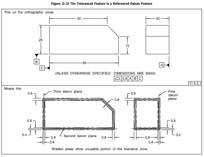
2) I think the lack of "ALL AROUND" or "ALL OVER" (which I think technically "all over" is what your inspector probably meant) is fine - see fig 11-21 in the new Y14.5-2018 (pasted below for reference).

3) Lets take your situation in two sections:
a) If you part is fully controlled with basic dimensions/general profile tolerances it may be difficult to inspect but it would be valid with or without* datum feature references. Presumably your part has some function or assembly critical surfaces so datum feature references would be recommended, but perhaps not required. Note* that if your general tolerance is the ONLY thing which controls your part (as in your hypothetical - no additional controls/tolerances) then no datum references would mean a tolerance zone encompassing all features of the specific width at basic location/orientation to one another. If your general tolerance is still the ONLY thing which controls your part, however now includes datum feature references but the datum features themselves are shown as the figure 11-21 below with no separate** control of those datum features (flatness, parallelism, etc.. **and are instead "wrapped" in the all over/general profile control) then they are subject to some special rules (often called self referencing). Y14.5-2009 does not make any mention of this, however Y14.5-2018 does in the figure below and associated section 11.4.3.1 - this is generally not recommended practice if it can be avoided however it is at least now covered if you go by the new 2018 standard (previously there was general consensus on how to treat it but no formal inclusion in the standard).​

b) If you part includes your general profile note WITHOUT datum feature references but is no longer the only thing which controls features on the part (has other datum features, tolerances, controls, etc..) then any feature which is subject to your general profile note will behave like any other surface with a datumless profile control. Your inspector is only partially right as the form of these features will still have to conform to the profile tolerance, however it will be free to rotate/translate in relation to your datum features and other features not controlled by the general profile tolerance.* In this case datum feature references would probably be recommended.​

general_profile_tolerance2_mc3auy.jpg


*As a matter of note, I am not 100% sure on the portions which are single asterisked. I would say that any portions which are controlled by the general tolerance - whether that is the entire part or portions of the part/interrupted surfaces - would act together as a single profile tolerance and be constrained in basic location/orientation to one another.

**Edited for clarity
 
Failed to mention that drawing also references ASME Y14.41, which states per 9.2.1 "Queried model values shall be interpreted as basic dimensions unless superceded by a toleranced dimension or defined as a reference dimension."

Thus we don't have a separate note or show any basic dimensions. The drawing itself is essentially a materials list and notes. (I'll add this info to the OP)

You do bring up some good points.
 
I don't have too much experience with Y14.41 however I know I would personally want either explicit basic dimensions or a note that said so. But that decision is ultimately up to you.

I know that was a lengthy post. The short version is that if your general profile tolerance is NOT the only thing which controls your part (even a single feature which has a separate tolerance) datum feature references in your general profile note would be highly recommended, unless you're okay with an unconstrained profile tolerance zone being able to float away from these other features without limit.
 
Let's take an example with a defined feature. Let's say a cube with a single hole going through it, with defined planes as datum A,B,C, and the hole position defined in reference to those planes. Same notes as above. Thus the planes that form the cube are governed only by the profile note with no reference to the datums. What do those "unconstrained profile tolerance zones" look like for the cube surface? I still envision an envelope between max and min profiles, and any cube that fits within that envelope would inspect good, as long as the hole is still good in relation to the datums. Is that a valid line of thought?

Also, thanks for your time.
 
The problem with this example is that the general note (2) uses datumless profile and because of that it's not clear if the features subject to it are to be treated as a pattern or individually. That's probably why the quality inspector is raising concerns and suggesting to add ALL OVER to the note. This would make the profile callout from the note fall under the pattern creation mechanism mentioned in para. 1.3.42, and the ambiguity would disappear.

(I assume that dimensioning and tolerancing is per Y14.5-2009, since the original post mentions para. 8.2.3 that doesn't exist in '94 version.)

Side note: While explicitly allowed by Y14.41-2012, profile in general note doesn't necessarily get along well with the Model Based Definition philosophy, especially when automated downstream consumption of the callout is desired. New version of Y14.41, which per my knowledge is going to be released this year, will offer a word or two on this topic.
 
Hmmm I'll admit thats a configuration I hadn't considered. I'm certainly not used to seeing it done that way, however you avoid self referencing datum features if the desire is to control the datum features themselves with the general profile note.

Unless someone else says otherwise I would say that is valid. The tolerance zones/features would only be unconstrained in that case if a feature is related to a DRF that is something other than |A|B|C| and/or not derived from |A|B|C|.
 
tim_member,

My personal opinion would be that a general tolerance applied through a note would be applied neither as a pattern or individually but instead as a single tolerance* the same as an all-over tolerance unless otherwise specified - regardless of datum feature references, or lack thereof. Unfortunately I am not backed up on this in 2009, however in 2018 the following verbiage (c) has been added to (a) and (b) which are mostly unchanged from 2009.

Y14.5-2018 said:
11.3.1.5 All Over Specification. A profile tolerance may
be applied all over the three-dimensional profile of a part
UOS. It shall be applied in one of the following ways:
(a) place the “all over” symbol on the leader from the
feature control frame as shown in Figure 11-10
(b) place the term “ALL OVER” beneath the feature
control frame
(c) place the profile tolerance requirement in the
general tolerance block or general notes

*Edit
 
chez311 said:
My personal opinion would be that a general tolerance applied through a note would be applied neither as a pattern or individually but instead as a single tolerance - regardless of datum feature references, or lack thereof.

I am not sure what you mean by this sentence. What I meant, however, was that as long as the profile callout in the note is not clearly applied on the all-over basis (or it doesn't use any of the mechanisms mentioned in the pattern definition that I referred to), one can make an argument that this single profile requirement applies to each feature individually, thereby merely controls form and/or size of each feature without controlling any relationship - implicitly or explicitly defined by basic dimensions - between the features.

The problem wouldn't exist if the profile tolerance referenced at least one datum, for example A, because then all the features controlled with it would be subject to simultaneous requirement, which is one of the pattern-creating mechanisms listed in 1.3.42. That's why I said the problem was due to the lack of datums in the profile tolerance specified in general note (2).
 
tim_member,

After re-reading your response, I'll concede that "ALL OVER" is definitely a pattern per Y14.5 and that if OP is going by 2009 then inclusion of such verbiage in the general note is probably a good idea since simultaneous requirements cannot be relied upon to essentially provide redundancy as the general profile tolerance is datumless. Even in 2018 it may still be wise, but at least the standard includes the OP's case as an acceptable note.
 
The note "ALL FEATURES ARE NOMINAL" is taken from ASME14.41-2012 Digital Product Definition Data Practices ,which I am surprised we have not seem more discussion on here, it is a RADICAL change to the way things have been done.
Section 1.4 "REFERENCE TO THIS STANDARD When data sets are based on this standard, this fact shall be noted in the data set or in a document referenced by the data set".
Section 6.1 states: "Parts shall be modeled at specified dimensional condition(s); for example, minimum, maximum, or mean. The dimensional condition(s) shall be specified in a note or in a referenced document".
Section 9.2.1 states: "Queried model dimensions shall be interpreted as basic dimensions unless superseded by a toleranced dimension or defined as a reference dimension".
Frank
 
Status
Not open for further replies.

Part and Inventory Search

Sponsor