Continue to Site

Eng-Tips is the largest engineering community on the Internet

Intelligent Work Forums for Engineering Professionals

  • Congratulations cowski on being selected by the Eng-Tips community for having the most helpful posts in the forums last week. Way to Go!

Profis - Anchor Parallel Issue

Status
Not open for further replies.

CURVEB

Structural
Jul 29, 2013
133
I am using Profis to check an anchor design and came across something in the code that seems confusing.

The application is a shear force applied along a concrete slab edge, but you could draw a parallel to any wood or light gage shear wall anchored to the top of a concrete stem wall. The force direction and anchor layout would be similar.

If you evaluate the capacity of a single anchor in this application, it might come in at around 3,000 lbs limited by the breakout strength of concrete. However, I found when adding more anchors the capacity does not increase. Reading through Appendix D of the ACI 318-11, this is consistent with the code equations. I believe this is because the factor Avc in section D.6.2.1 does not increase as you add anchors further down the row.

My questions are:
1) By spacing anchors further apart, do you eliminate the "group action" so that you can base the design of the line of anchors on the individual capacity x number of anchors? At what spacing would you consider this to be an option?
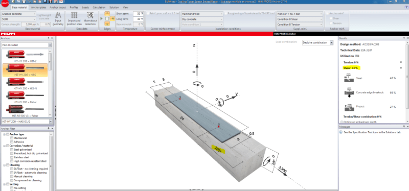
2) The equations (and software) indicate that if you have no nearby edges the force would be based on the "parallel to edge" condition of D.6.2.1(c), which is twice the capacity of an anchor loaded perpendicular to the edge. At what edge distance would you consider there to be no breakout effects? See the 2 attached screenshots from Hilti showing an infinite edge distance with double the capacity of a 100" edge distance.
 
 https://files.engineering.com/getfile.aspx?folder=fad24841-97fb-47a6-8c3b-79aeb98d26f4&file=Anchor_With_no_edge_distance.PNG
Replies continue below

Recommended for you

Here is the other file:
Anchor_with_edge_distance_lvo4xf.png
 
Given the typical 'spread' of the breakout surface being at 1:1.5, you would need anchors spaced at 3 times the edge distance (where edge distance is the edge distance perpendicular to the parallel to edge force) for no interaction.

Basically you don't get a linear increase because the individual anchors breakout surfaces overlap.

The problem in your specific example is that the edge distance to be used in calculations for the parallel case is not infinite, it is 5". Consider it like this, the edge distance is always towards the closest edge, for the parallel case the capacity is simply 2 times the capacity as if the same load was applied towards the edge. There are examples within the PCI Design Handbook that demonstrate this principle. Not familiar with Profis, but Simpson software for example when you drill down into the calculations also demonstrates this principle.

If you truly have a large edge distance, then concrete breakout is unlikely to govern, other limit states will govern for shear.

In ACI, it really isn't clear with the wording they used, however this is really what they meant.
 
I agree that the edge distance is 5". What I'm struggling with is that the equations don't account for an increase in the Avc factor based on having multiple anchors. Avc appears to be limited to the front anchor only, so according to the equations, I don't see how you can get any increase in capacity by adding anchors behind the front one.
 
At times, I've "ignored" the anchor closest to the edge, if the anchors with further edge distances work without any contribution from the closest one, then all good. But that's only been in desperate times.
 
The equations account for having multiple anchors parallel to the edge via the A_vc/A_vco term in equation D-30 or D-31. A_vc is the total breakout area for all anchors being considered inclusive of any limitations imposed by thickness or corner effects reducing the breakout area, A_vco is for a single anchor not considering any limiting thickness/edge effects. This ratio is therefore the equivalent number of anchors considered, the factor by which you increase the capacity of a single anchor (being the capacity Vb).

If you are talking about say a 2 x 2 anchor group as an example then the anchors closest to the edge govern for concrete breakout for load parallel to the edge as you progressively increase the load, and hence the edge anchors govern for the connection capacity as a whole. You can place as many additional anchors further form the edge and it will not change the failure capacity. It can seem counter intuitive as in most other scenarios like steel design if you add more or bigger bolts it equates to more capacity, but the overall capacity is simply based on the weakest link, in this case the two anchors closest to the edge failing in concrete breakout.

If you worked out the capacity for 2 anchors parallel to the edge say 100mm for the edge and the same two anchors 200mm from the edge, then those closest to the edge naturally would have a lower capacity. If these two sets of anchors are part of the same fixture then as you ramp up the load the anchors closes to the edge fail first and hence govern the overall capacity of the connection. So if shear was evenly distributed between both rows of anchors, then the capacity would be twice that of the row of anchors closest to the edge.

As jayrod12 noted, you can simply ignore the front anchors, but you then need to consider the full load on anchors further from the edge, however also need to be aware that the load might then be applied eccentric to the remaining anchors which has additional reduction factors ( the term noted in D.6.2.5, with e'v being the introduced eccentricity due to some anchors failing earlier on as the load increases). This concept is shown for the load perpendicular to the edge case in ACI318 in figure RD.6.2.1(b) CASE 2 for example, similar behaviour can be implied for the parallel to edge cases. Depending on your arrangement you may or may not achieve any further capacity from these considerations. As long as you appreciate that the front anchors are failing for the loads to redistribute to the rear anchors, and the damage that might occur in achieving this.


I see in the 2011 version of ACI (having now looked at it specifically) that they actually added some pictures to explain the edge distances to be used for the parallel case, I'd previously only used the 2008 version where it was quite cryptic and I'd seen many people take the distance being parallel to the next edge (close to the infinite edge you first mentioned).
 
Agent,
Thank you for the great post. I think I may still be missing something though. In your example of the 2x2 anchors, I agree that those closest to the edge will govern the connection, however, what if you take those 2 further way anchors and line them up with the other 2, so you have a row of 4 bolts, all the same distance from the edge. Assuming these 4 bolts are spaced far enough not to interact with each other, wouldn't this condition give you twice the capacity as the 2x2 scenario? If so, how is that accounted for in the breakout equations?
 
Hi, yes it would give you twice the capacity as per your thinking.

Its accounted for in the equations because A_vc has doubled (double the breakout surface with double the anchors), and A_vco is the same as its based on a single anchor. This assumes that the original two anchors did not interact with one another of course.

A_vc is the total breakout area of all considered anchors, A_vco is always for a single anchor (4.5c_a1^2 for shear from D-32).

If you have a high degree of interaction the capacity tends towards the capacity of one anchor as the breakout surfaces from the two anchors have a higher degree of overlap (or can be lower if thickness of the member or nearby corners affect the breakout surface), and with multiple anchors with no interaction the capacity tends towards that of 4 single anchors. Think of the A_cv/A_cvo as a ratio of how effective your group is in comparison to a single anchor with no edge or thickness effects.

If you do one or two scenrios by hand you will see for example if you have two anchors spaced at 3c_a1 spacing there is no interaction between the two anchors, A_vc/A_vco ratio will be 2 assuming no edge or thickness reductions. If you were to add another third anchor between these two anchors, the ratio is still 2, you are not increasing the capacity of the concrete breakout mechanism as you are not increasing the projected area of the concrete that is failing in this case. You are only increasing the steel capacity checks in this case as load is shared over three anchors, but load for concrete failure is still occurring over the same projected area.

Hope that's clear?
 
Yes - it makes sense. I'll still need to chase down why the software doesn't seem to be considering this in their check but what you're saying sounds right to me.
 
Can you provide the output (PDF) for the hypothetical case we are discussing so we can see if there are any obvious issues with input/output as to why you are not seeing the doubling of the capacity?


Here are the 2 files, one showing a single anchor, and 1 showing a second anchor more than 3*Ca1 away from the first. Reviewing the results, it appears that the software considers all of the parameters to be identical between the 2 situations. I would contend that with 2 anchors, the term Acv should be double what it is for a single anchor, resulting in double the capacity. Please let me know if you agree - and if so I will probably follow up with Hilti's engineers for further confirmation. Thanks.
 
 https://files.engineering.com/getfile.aspx?folder=2c6fe464-161b-4a75-8db1-4ac2cc17d4e3&file=Anchor_Edge_Breakout_-_Multiple_Anchors.pdf
I think its because with that 10" wide test arrangement you are possibly being governed by the perpendicular case and being influenced by three edges, i.e. its taking c_a1 as 16". So the capacity is governed by the first anchor breaking off the 16" by 10" wide section in front of the anchor, rather than mobilising a parallel breakout surface to the side.

Additionally with the narrow section of a fixed height if all the load was on either anchor they both have the exact same capacity under the above breakout scenario. You are essentially breaking through a 10" wide x 24" deep area with either anchor, so capacity is the same.

To test the philosophy, increase one of the 5" dimensions & the 16" dimension to a lot higher number to isolate the parallel behaviour. You should then see the doubling of the capacity.

In ACI318 there is a special case when 2 or more edges influence the breakout surface, refer to D.6.2.4 for this case (and associated figure RD.6.2.4). I believe with the dimensions in your test scenario you are evoking this case.
 
Status
Not open for further replies.

Part and Inventory Search

Sponsor