Eng-Tips is the largest engineering community on the Internet

Intelligent Work Forums for Engineering Professionals

Propeller Pitch Distribution

Status
Not open for further replies.

TugboatEng

Marine/Ocean
Nov 1, 2015
11,388
1
36
US
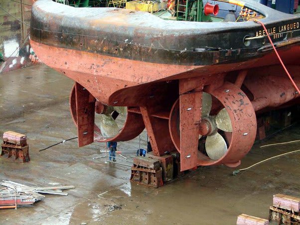
My application isn't a pump but it's similar. Propeller on my boats are distributed pitch props in nozzles. I am having an issue where the low speed load from the prop is too high. Typically to reduce load, one would re-pitch the prop but that would also reduce the high speed thrust. This is a varying pitch prop so it has more pitch towards the hub and less towards the tips. Am I wrong to think that increasing pitch towards the hub while simultaneously reducing pitch at the outer diameter would, maybe, decrease thrust at low rpm and maintain it at high rpm?
 
Replies continue below

Recommended for you

Well, Tug . . . it depends, "I think".

Would that not have a great deal to do with how much time the vessel spends at low speed as opposed to full or higher speeds?

The mind picture I'm using is that when a vessel moves from rest to slow speed ahead is that the prop will at first develop thrust on all of its surfaces, some areas more, some less.

As way is put on the velocity of water flowing past the propellor will in some areas of the prop surfaces be less than the screw advance, and in these areas the prop will develop thrust.

Where the velocity is greater than the screw advance, the prop surface will actually do work to slow the water velocity down due to the negative angle of attack.

If I'm grasping your question correctly, you're looking to do something about this thrust/drag imbalance at low speed.

I'd "think" the answer lies somewhere in an analysis of the vessel's normal use; would any mods to reduce this imbalance at low speed be deleterious at higher speeds, i.e. tug boats typically spend a lot of time develop full thrust at zero to very low water velocities . . .

I'll stop here, as I'm already pushing the limits of my wheelhouse . . .


choice , always being a compromise, w

CR

"As iron sharpens iron, so one person sharpens another." [Proverbs 27:17, NIV]
 
I've always been surprised to find out that propellers, marine and air are not really a calculated thing, but something someone makes and then tests it as far as I can see.

but isn't load connected to speed? So just turn the propellor slaower to reduce load.

I'm struggling a bit to work out what is meant by "load" - shaft power? or torque or what exactly?

Or does the efficiency drop off so you need more power for the same thrust?

I still strongly suspect this is in the hands / art of the vendor and that they publish curves of speed vs power, efficiency and thrust.
Are all you props shrouded?

Drawings or pictures always help!


Remember - More details = better answers
Also: If you get a response it's polite to respond to it.
 
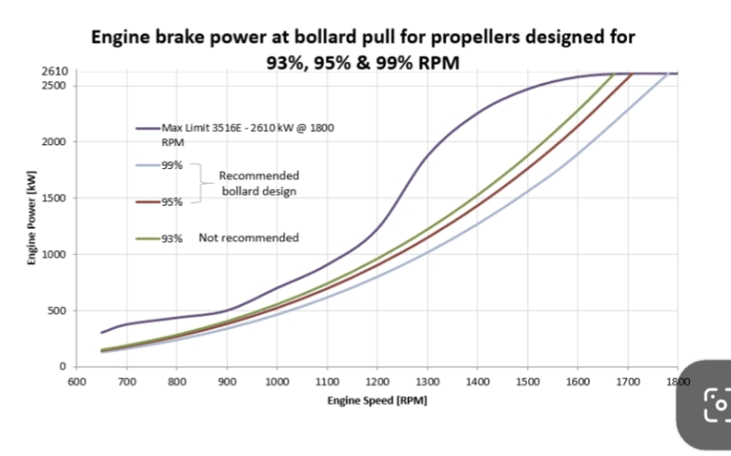
For tugs the propeller is pitched so that the propeller curve intersects with max engine power while the vessel is stationary.

Screenshot_20240626-065629_rlwtn2.png


I am having problems in the 1200 rpm and under region where the engine power doesn't sufficiently exceed the propeller power which causing slow acceleration and stalling.
 
I'm finding it difficult to parse your question. Increase vs decrease pitch. I think I know what you mean but it is like increasing or decreasing vacuum. Does that mean higher or lower absolute pressure?

Then it occurs to me that when you say high and low speed are you referring to prop speed or boat speed? In any case my thinking is that the blade pitch near the hub has little effect at low speed. At high speed of the boat you want a high pitch near the hub to reduce drag. The centrifugal pumping action at high prop speed becomes significant. I'll stop there until further clarification.
 
I am referring to prop speed. Assume the boat is stationary. This is a ducted propeller which should minimize the centrifugal action.


My question: Is it possible to pitch a propeller to reduce power at low prop rpms while maintaining peak power at high prop rpms?
 
I was preparing to have a conversation with a propeller engineer. We had the conversation today, lots of questions answered. My problem is not solved.
 
Tug, how about discussing it with an experienced airfoil engineer.

It is a capital mistake to theorise before one has data. Insensibly one begins to twist facts to suit theories, instead of theories to suit facts. (Sherlock Holmes - A Scandal in Bohemia.)
 
experienced airfoil engineer

Might be helpful; major problem though is that an airfoil engineer does not have to deal with the problem of cavitation, whereas a [fluid] propeller engineer does.

CR

"As iron sharpens iron, so one person sharpens another." [Proverbs 27:17, NIV]
 
OP,
This is coming from my brain trying to understand this on a 2 hour drive, so it may be total garbage but it made sense to me.
Hydro-props are limited in airfoil design due to aforementioned cavitation. Whereas an air, a combination of lift and drag can be used to transfer energy and momentum, in water, since lift=low pressure=cavitation, only the drag regime can be used to effectively transfer forces. This is not purely a downside, since water is much dense than water, a considerable amount more energy per unit volume can be transferred. A hydro-prop's pitch is the balancing act between transferring momentum p=mv and force/energy KE=1/2mv^2. This balancing act (v vs. v^2) shows up axially and radially. It shows up radially with the variable pitch of the hydro-prop due to the relative velocities of the inner and outer portions of the prop needing to be balanced so work is transferred across the blade radial length. It also shows up in the graph you provided in the exponential growth (v^2) of the hydro-prop power vs rpm.
Based on the information you provided the design constraints on a tugboat's hydro-prop design are:
-The most efficient transfer of power and momentum must be at or near the peak power of the propulsion unit.
-Exhibit a performance curve across the rest of the rpm range that most closely matches he propulsions unit power
without exceeding, ie. stalling or losing acceleration.
The graphic you provided shows the prop most closely matching the propulsion unit's power across the rpm range is the 93% but is too close, so any degradation in the propulsion unit's performance would mean stalling or lose of acceleration, so it is not recommended.
The 95% and 99% show a loss small loss in efficiency compared to the 93% across the rpm range but provides a buffer to allow for less than optimal propulsion unit performance, lowering the risk of stalling.

To answer the main question, will changing the pitch alone provide the performance change you are looking for? No
Is it possible to design a hydro-prop providing the performance you are seeking? I think you could but would likely result in much higher in efficiencies. I suspect these are standard hydro-prop designs for tugs that propulsions units are matched to performance wise.

To address your problem of stall and lack of acceleration below ~1200rpm. It appears either a lack in rated propulsion unit performance or an unaccounted for inefficiency in the transfer of power from the engine to the hydro-prop is at issue.
 
Yes, the problem is a lack of performance of the propulsion unit. The engine manufacturer tuned the smoke limits to exactly follow the prop curve so there is zero margin. The engine is emissions certified and the manufacturer refuses to adjust the tune. Hence I am here looking for ways to reduce the performance of the prop without diminishing the peak bollard pull.
 
So, performance curve is fixed, propulsion unit is fixed, recommended prop type is fixed. Nice of the engine manufacture to give themselves "going green" gold star by passing the problem on to you.
Since it is ducted, is there a way you can restrict flow at low rpm / velocity? Something like a reverse governor, where a mechanical force restricts the flow but as you develop rpm / velocity the flow stream holds the restriction open, or the mechanical force is reduced somehow.
 
The issue as I see it is that a marine propellor tries to create a column of water all going at the sane speed in order not to create vortices and slip regions when part of that column is going faster than another part.

So mess with one part of the prop and you will lose max thrust and efficiency falls.

Could you perhaps inject air into the ducted region at low speed? That will reduce density and hence power, allow the engine to ramp up then slowly reduce air injection?

Maybe?

Remember - More details = better answers
Also: If you get a response it's polite to respond to it.
 
Can self-modulating control surfaces be added to the tailing edge of the duct?
and to add to the ventilation / air injection idea, instead of piping, can a non-rotating sleave be added around the rotating z-drive shaft as a conduit to get air from the hull to the pod with a rotating coupling to direct the air into the duct?
 
How much air would it take to ventilate a 10 foot diameter propeller?

Boats with ventilated props use the engine exhaust but this prop's hub is 13 feet below the surface. That back pressure would exceed our engine's limitations.

Self-modulating is a challenge. I can't afford to lose more than 1% of performance. Spring loaded dampers would likely cause too much reduction in performance.
 
So it looks like this?

main-qimg-dcf0f01cca34632ac2ff856dbddc27be-lq_bylh9k.jpg


You would need a decent sized air compressor alright. Amount of air I really don't know but could be quite low.

Remember - More details = better answers
Also: If you get a response it's polite to respond to it.
 
Status
Not open for further replies.
Back
Top