Tek-Tips is the largest IT community on the Internet today!

Members share and learn making Tek-Tips Forums the best source of peer-reviewed technical information on the Internet!

  • Congratulations cowski on being selected by the Eng-Tips community for having the most helpful posts in the forums last week. Way to Go!

Proper drafting standards for angles 2

Status
Not open for further replies.

martinwilson

Mechanical
Joined
Jan 6, 2012
Messages
1
Location
US
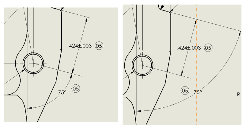
I have always been taught that if the angle on a drawing would make the view look messy that you can attach the angle to the linear dimension. I cannot find any literature in the GE, ASME or Saab drafting standards books that explicitly tell me the correct form. Can someone tell me if the left version is legal and if so, is there any literature that explicitly represents this?

Capture_pvg3cg.png
 
The one on the left measures literally nothing. So, the one on the right, I guess.
 
Both are correct, though the first example makes for a cleaner drawing.

"Know the rules well, so you can break them effectively."
-Dalai Lama XIV
 
It is this sort of issue that Feature Control Frames were invented - to specify the exact basis from which variations are to be inspected.

However, since the expectation is that a linear dimension with two extension lines represents an exact, perfect, and unvarying intention of parallel lines, then in any Euclidean geometry course they are exactly the same.
 
Hi All,

Looking at specifications like this gives me flashbacks to my days as an inspector, trying to find a repeatable way to measure stuff like that or program a CMM to do it (and often finding that it was impossible).

Evan Janeshewski

Axymetrix Quality Engineering Inc.
 
martinwilson,

TheTick is correct. An angle measurement must be made from a flat surface, preferably a datum feature.

--
JHG
 
Status
Not open for further replies.

Part and Inventory Search

Sponsor

Back
Top