Continue to Site

Eng-Tips is the largest engineering community on the Internet

Intelligent Work Forums for Engineering Professionals

  • Congratulations KootK on being selected by the Eng-Tips community for having the most helpful posts in the forums last week. Way to Go!

Proper Interpretation of Results

Status
Not open for further replies.

APG817

Civil/Environmental
Aug 13, 2018
12
Hi again,

I believe I'm modeling my design properly, but I'm having trouble interpreting one of the results. I've attached the file for reference.
Essentially I have a simple system with a Catchment area feeding into a Catch Basin which flows into a detention pond (36" pipe 25 ft. long). This storage pipe has an invert of 40.55, and the top of the pipe is at approximately 43.50'.
The storage pipe outlets via a 6" culvert, and flows into a sump. The pump overflow is at 43'.

Now for the results. The report shows that the pump's overflow (el. 43') is being used during the storm, but the Detention System shows a Peak Elevation of only 40.61'. To the contrary, I get a warning that my detention pond has "Submerged Pond CB1 Primary Device (inv. 44')

If the upstream to downstream flow is Catch Basin > Detention > Sump, how can I simultaneously be A) Triggering my pump overflow downstream at 43' B) Overtopping my catch basin invert at 44' and C) Have max elevation in my detention pipe of 40.61.'

It makes sense that the pump's overflow is being triggered, AND it makes sense that the catch basin has some overtopping at the invert. What doesn't make sense is how my detention pond, which SHOULD be almost completely full, has a peak elevation of 40.61'.

Please see attached hydroCAD file.

Thanks for any help in advance,
 
 https://files.engineering.com/getfile.aspx?folder=5ba4c990-3653-4a80-a848-1f1619ae5941&file=Project_help.hcp
Replies continue below

Recommended for you

Please read the messages more carefully:

It says "Submerged Pond CB1 Primary Device #1 OUTLET by 0.06'". Since the outlet invert is 40.55, adding 0.06 gives 40.61 which matches the peak WSE reported for the downstream detention node D1.

As for the higher elevation in the pump chamber P1, this occurs because you need to use a tailwater-sensitive routing procedure as indicated by the warning message. This is also required to handle the pump's switching hysteresis (as indicated by another message when you created the pump).

[81] Warning:

{node} Exceeded Pond x by x.x' @ x.x hrs
--------------------------------------------------------------------------------
At some point during the routing, the node's water surface elevation has exceeded the water surface elevation of an inflowing pond, indicating a possible tailwater dependency. The message shows the maximum amount of reverse head and the time at which it occurred.

Important: The pond routing is not altered by this situation, even though the higher tailwater may in reality cause a reduced discharge. To remedy the situation, select a pond routing method that is able to handle tailwater effects, such as the Dynamic Storage-Indication method.

Note: This and other warning messages can be triggered by basic routing failures, such as oscillations. If any oscillation warnings are present, these must be resolved first.


Peter Smart
HydroCAD Software
 
Hi again psmart thanks for your analysis - I appreciate the feedback and will be more diligent in analyzing my error messages. I suspected the condition might be tailwater-sensitive, and attempted to use DSI routing, however that created significant oscillations in my detention hydrograph, which were not remedied by adjusting either the time step or the finer routing. Per the Oscillations info page, I think my problem is:

2) Oscillations can also be triggered by overfilled storage, or by other conditions that cause an abrupt change in any stage-storage or stage-discharge curve. When modeling a very small "pond", such as a catch basin, better results may be obtained by using a "zero-storage pond" and neglecting the volume.

While this makes sense, I'm not sure how to adjust my model, since the system is designed to be 'overfull.' The pump overflow is an inch higher than the top of my storage pipe, meaning that when the overflow is used, water is filling the dedicated storage pipe entirely and even backing up further upstream into the incoming culvert.

edit: Maybe I will do as suggested and treat my sump manhole as zero-volume, although this doesn't seem entirely correct.


Although the overflow (presumably a weir) may be somewhat higher than the pipe storage, there has to be a way for the water to get from the pipe storage to the overflow, and you should include that volume as part of the pond storage. For example, if the overflow is at the top of a riser or manhole, then use a vertical cylinder to define the volume. Whatever the volume will be as the pond overflows, make sure it's fully represented in the defined storage.

Peter Smart
HydroCAD Software
 
The zero-storage pond option is generally preferable for very small volumes, since these small volumes provide minimal attenuation while being prone to instability.

However, you generally DO need to define the storage of a pump vault, otherwise you are prone to get rapid fluctuations in the WSE as the pump switches on and off. That's the purpose of the pump chamber - to reduce the pump cycling - so you need to include it in the model in order to get a meaningful simulation. For details see

Peter Smart
HydroCAD Software
 
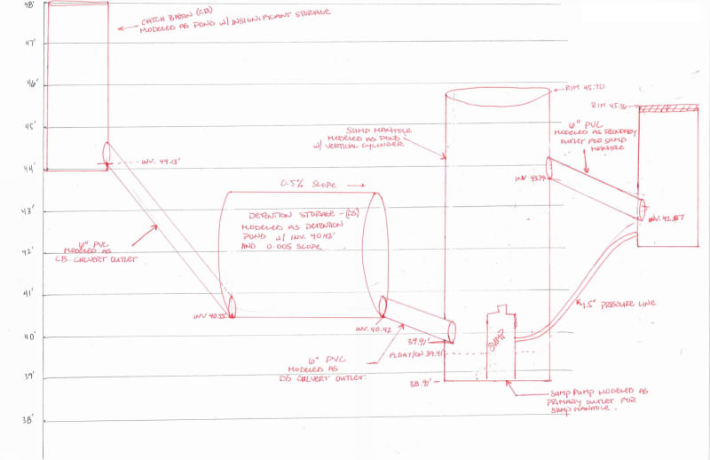
It took me a couple hours this morning but I've got my model working correctly. My main issue was that I hadn't factored in a tailwater dependency. But a bigger issue was that reverse-flow was occurring in our downstream node! I've attached a picture of our routing design.

Sump_Overflow_-_flap-valve_needed_otbji2.jpg


During a large storm, water is able to get out of the Rim of our outfall, despite flow traveling back through our designated overflow. What we didn't account for is a smaller storm that did not reach our rim. This could cause a repeat cycle of reverse-flow back into our sump, which would burn out the pump until water percolated back into the ground. We're adding a one-way flap-valve in our design to correct this issue.

We've fixed our design and are able to model it correctly.

Thanks psmart!
 
Status
Not open for further replies.

Part and Inventory Search

Sponsor