Continue to Site

Eng-Tips is the largest engineering community on the Internet

Intelligent Work Forums for Engineering Professionals

  • Congratulations SSS148 on being selected by the Eng-Tips community for having the most helpful posts in the forums last week. Way to Go!

Proper simulation of frame analysis

Status
Not open for further replies.

firstoption

Structural
Aug 25, 2016
49
It's been so long i've worked on structural, i can't believe i'm in need of assistance for something so (seemingly) basic


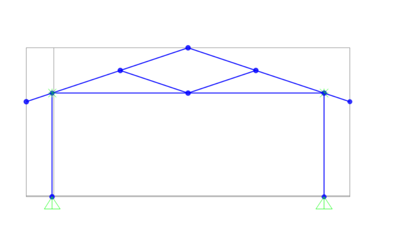
I am analyzing a simple 2D frame (two walls, two rafters, one joist, two interior braces). Pinned connections at base.
When i run the analysis, i obtain rational stresses for the sections, BUT i get a ridiculous displacement output (which makes no sense considering the relatively low stresses), roughly 40 TRILLION inch displacement.

I realized it's because it's technically a model of an unbraced frame that i get these results.
But how exactly would i simulate the extra rigidity that the frame realistically has (due to the other members out of the 2D plane)?
I can't put a brace between the top plate on one side to the sill plate on the other. Can't add another displacement constraint anywhere else as it'd be inaccurate.


Any help would be appreciated
 
Replies continue below

Recommended for you

Could you post a sketch of what you have? Is the excessive deflection in the out-of-plane direction?
 
Your model is unstable. You need to restrain the top of ONE wall the against sideways displacement since you have not modeled the stability inducing roof diaphragm. Think about it - if you built something like that without a roof diaphragm, you could push it over easily.
 
"pinned connections at base" ... how can this react lateral load (without falling over)?
and it's not enough that you say "but there is no lateral load", FEM needs stiffness even if there is no load applied.

another day in paradise, or is paradise one day closer ?
 
sketch_yurrka.png

here is the sketch

@XR250
thanks, that's kinda the confirmation i needed. Just wasn't sure how to simulate this. (i eventually restrained both top plates and was debating on just doing one)
 
rb1957 said:
"pinned connections at base" ... how can this react lateral load (without falling over)?
and it's not enough that you say "but there is no lateral load", FEM needs stiffness even if there is no load applied.

that's not the issue. fixed bases also resulted in the same problem
 
you should only restrain one top plate or you will get erroneous results
 
In the plane of this sketch, I'd choose one of the following:

1. Have a kicker going between the column and that girder the column frames in to.

2. Have a fixed (i.e. moment connection) between the column and that girder the column frames in to.

3. Make the bases fixed and have a stiffer column as the cantilever.

4. Have a shear wall system to brace this.
 
"that's not the issue. fixed bases also resulted in the same problem"

agreed, now we've seen the sketch (not a simple frame IMHO) it's not The problem, but it is One problem.
the frame is redundant, assuming the joints are all pinned. IMHO, the joints need to be fixed ... if truly pinned then nothing will work.

restraining the top plates hides these problems with the frame. hopefully the force on these restraints is small, and no side force is applied.

another day in paradise, or is paradise one day closer ?
 
What does the 3D structure look like? Are there walls on all four sides of this building or is it open on one/two sides?
 
Status
Not open for further replies.

Part and Inventory Search

Sponsor