Continue to Site

Eng-Tips is the largest engineering community on the Internet

Intelligent Work Forums for Engineering Professionals

  • Congratulations KootK on being selected by the Eng-Tips community for having the most helpful posts in the forums last week. Way to Go!

Propped Cantilever Beam LTB AISC 1

Arun4567777

Structural
Aug 11, 2020
87
I have a propped cantilever beam. The total length of the beam is 15m with a 4m overhang. At the two supports its is bearing on the concrete columns with bottom flange bolts. The beam is totally unrestrained. To my question, AISC provides no K factor for LTB. Since at the suports my top flange is laterally not supported. Should I only use Cb=1. How AISC takes care for the K factor like in BS Codes. Excuse my drawing
 
Replies continue below

Recommended for you

AISC is less thorough considering LTB in cantilever beams than BS or Eurocode provisions. To meet the minimum requirements of the code, you simply use Cb=1 and Lb = L. AISC assumes full torsional restraint at the support and full depth stiffeners at the ends of cantilevers (unless some other torsional restraint is present).

The SSRC, in the Guide to Stability Design Criteria for Metal Structures (which isn't a code document, but is a common reference for US engineers) includes some provisions from research which end up echoing the BS code provisions for cantilevers based on the backspan condition, torsional restraint at the support, restraint at the cantilever tip, and loading condition. AISC's "steel interchange" magazine column in 2005 also referenced Nethercot's coefficients addressing the same issue.

It's my opinion that AISC doesn't go to that level of complexity because for many common building structures and detailing practices, Cb=1 works. I tend to deal with non-typical structures and detailing, so I apply the K factors on top of my AISC (or AASHTO) calculations.
 
Last edited:
Thanks for your response. However, this will require manual calculations every time to modify the moment resistance for LTB since the K factor is not in the equation.
 
Is this an existing / temporary beam? If not, could you put stiffeners in over the supports to stabilize the top flange at those locations?

What is the nature of the load? Uniform? Concentrated at cantilever tip?

We've discussed similar things a few time here in relation to temporary lifting beams.
 
Several years back I had a cantilevered monorail to lower a large telehandler down a mine shaft. I used the Eurocodes for design... I couldn't find anything local for guidance.
 
AISC 360-16 F1 states, "For cantilevers where warping is prevented at the support and where the free end is unbraced, Cb = 1.0."

Load placed on an unbraced top flange will produce a tipping effect, but load suspended from an unbraced bottom flange (e.g. monorail) will have a stabilizing effect. The AISC Spec commentary on F1 states that you can conservatively set the square root term in the LTB critical stress, Fcr, Equation F2-4 equal to 1.0 for the case of unbraced top flange loading.

As others have said, best to provide full depth vertical stiffeners at the supports. This is required by AISC 360 J10.7 at unframed ends of beams that aren't restrained against rotation.
 
@KootK This will be new structural assembly. How stiffeners at Supports will stabilize the Top flange.Its a uniform load on top flange.

@ RattlinBog Yes I also studied this. Code tells to provide stiffeners at ends and not at Supports. How these will help to stabilize the Top flange. I am using a software to design these beams. To do it manually it will be very time consuming. As per BS code for such a case with a destabilizing load, the K factor has to be 7.5.
 
The stiffeners will cantilever up from the bolted connection to restrain the top flange laterally. I reckon that's your path here. The stiffeners don't even need to be full height in my opinion. Just close.
 
I'm not familiar with the BS code. The AISC steel construction manual describes the use of web stiffeners to provide stability for beams continuous over columns in Part 2 - "Beams and Girders Framing Continuously over Columns." Fig. 2-2d in the 16th ed manual. It's commonly used.

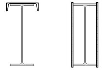
You said something about a drawing in the OP, but I don't see one. Not sure what your loads are, but this sounds like a large beam. Do you have the freedom to reinforce the beam (assuming it's a WF) with either a channel cap or with side plates to form a closed box section? If your goal is to deal with LTB, those options would be massively helpful with increased J, Cw, and Iy. If you had a fully closed box section, you'd really be in the clear. Again, not sure if either of those would be practical for you.

reinforcement.jpg
 
I have a 1.5m deep beam with an unrestrained top flange at the supports. You suggested adding a stiffener to restrain the top flange will suffice. Do I still need to make the square root term equal to 1 to account for lateral-torsional buckling resistance, or is the stiffener alone sufficient for torsional restarint at support for top flange?
 
There’s a few FAQ entries under the AISC forum that pertain to this question

I think quite a few of the AISC FAQs I did are missing, particularly one on the HSS design thickness change, and another on steel beam design that compiled some of the Cb articles, and covered the history, (that’s a Ted Galambos Engineering Journal Article…)

Fundamentally, the Canadian uses a K factor, the AISC approach kind of conceals that factor in the base equations and uses Cb as a surrogate, the effects are (intended to be, I Think) equivalent. There are cases under AISC where you have to go under the hood and wire things together manually. Cantilever beams being one of them, there’s a seminar on Cb referenced in the FAQs, and you can get into further depth from there if you like.

How are we doing subscripts now? And the li entries are busted too.
 
It's here:

I feel like some of the FAQs are missing, but there's at least maybe a quarter to a half of them that survived the forum transition.

For you - there's an AISC seminar on Cb you can watch for free, indirect link:

That's not directly on your question, but the background on Cb should be useful.

There's also Steel Design After College (again, coverage on Cb).
 
I have a 1.5m deep beam with an unrestrained top flange at the supports. You suggested adding a stiffener to restrain the top flange will suffice. Do I still need to make the square root term equal to 1 to account for lateral-torsional buckling resistance, or is the stiffener alone sufficient for torsional restarint at support for top flange?
Up to you and what you're getting for analysis results. Setting the square root term to 1 can be conservative, especially with larger J values. I can't comment on your particular design as I don't know any of the details or key variables like Lp, Lr, rts, etc. I'm also not sure which code you're actually using as a few different ones were mentioned.

You said something about hand calculations taking too long, but I suggest playing around with some of the flexure equations in Excel/Mathcad to see what you get with different section properties. If it's an option, a larger St. Venant torsional constant, J, should help you tremendously if you're seeing LTB issues.
 

Part and Inventory Search

Sponsor