Continue to Site

Eng-Tips is the largest engineering community on the Internet

Intelligent Work Forums for Engineering Professionals

  • Congratulations KootK on being selected by the Eng-Tips community for having the most helpful posts in the forums last week. Way to Go!

Propped Retaining Wall Sliding?

Status
Not open for further replies.

psychedomination

Structural
Jan 21, 2016
114
Hi there,

I’m working on a cesspit project. The cesspit will have an open bottom to allow for natural seepage.

My question is how sliding will work for a structure like this?

It is essentially a retaining wall propped at the top and bottom. But due to the bottom being open, would this structure be susceptible to sliding? Or would the opposite forces balance the sliding (even though it has an open bottom)?
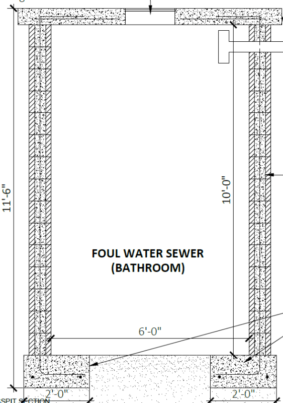
Cesspit_-_Copy_aihqee.png
 
Replies continue below

Recommended for you

I would think you need to design this for the condition that the tank is empty, and because it's not tied from side to side you would have a major sliding problem.

I have not designed a cesspit, but we've done similar for stormwater infiltration tanks. In that case we place a footing tie across the tank every 10'-15' as required to take that compression. This tie is designed as a column for distributed reinforcing and ties. Then make sure the footing is designed as a horizontal beam to span from tie to tie. There may be other ways of looking at this but I am not aware.
 
@ryaneng

Thanks for your comment, yes I'm analysing this as an empty tank with an open bottom. Based on some quick calculations, the sliding force is too high (if the bottom is susceptible to sliding).

However, I'm trying to understand how the sliding mechanism works if the wall is propped at the top? Does the propped top help to reduce the sliding force acting on the base? As in, would I split the total sliding force in half, where 1/2 is acting on the top and half acting on the footing? And therefore only need to consider 1/2 of the sliding force acting on the footing as this is the only location not fully restrained.
 
Where would the 1/2 at the top go to? If it's tied into a different lateral system that delivers it to the ground a different way, then maybe. But otherwise no, you cannot just wave away 1/2 of the lateral load.
 
The soil load to the bottom would be greater than 2/3 of the total force from active (ka) pressure (triangular pressure distribution). Because the top is restrained, you'd get at least some of the soil that would be in an at-rest (ko) condition. That's assuming the bottom is allowed to move enough to reach the active condition, otherwise you should assume at-rest pressure for the full height.

Rod Smith, P.E., The artist formerly known as HotRod10
 
@BridgeSmith For the sliding load assumptions, I'm assuming at rest earth pressure the entire height.

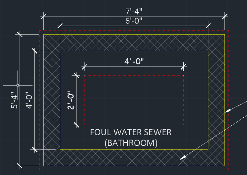
For clarity, I've shown a plan drawing of the tank and the footing extents. The footing extents are shown in the dashed red line.

Screenshot_2022-11-24_162722_-_Copy_imv3r5.png


As shown, the footing is around the entire perimeter of the pit and the seepage hole is 4'x2'. As the footings are tied together, would the opposite sides not resist the sliding? The cesspit will be buried in the ground.

Is there a quick check for this? Would it be correct to assume that the open 4' section is a beam and make sure there's enough reinforcement to resist bending? If it fails, either include more reinforcement or put an additional footing tie-in to reduce the span as mentioned by @ryaneng?

Any advice would be appreciated.
 
As long as the footing can transfer the load to the outer two pieces, and then across to the other side, I don't see why sliding would be an issue assuming the soil level on each side of the pit was the same.
 
psychedomination said:
It is essentially a retaining wall propped at the top and bottom. But due to the bottom being open...

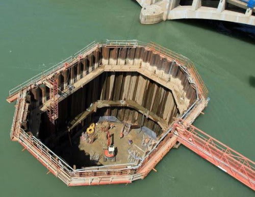
No, it's not going to slide, for the reason jayrod12 stated... since it is more like a cofferdam (open bottom, no concrete seal) than a retaining wall:

Cofferdam_Example-500_vbf24n.jpg


What could happen is the wall(s) collapse inward because of soil / ground water hydrostatic pressure.
 
There is a rectangular ring at the bottom which can be reinforced to resist the lateral pressure.
 
In Houston, pre-cast box culverts (RCBs) are used as wet wells all the time.

You could possibly get 6x4 RCB's that are rated for 12ft burial depth. And boom...you're done.

You can put a top slab on the RCB's if you want; or pour a bottom slab to reduce the seepage hole down to 4x2.
 
Here is the Cast in Place Version....

And Here is the Pre-Cast Version


Ohh...Sliding is not an issue if you have fill dirt uniformly around the structure. Your worst loading condition is the tank empty condition with uniform compression from the soil attempting to crush the well.

Another load case that may be possible is this....if you open cut the excavation and then fill your well with water to test for water tightness; you can get uniform pressure pushing outwards. (In some jurisdictions you are required to design for this scenario.)
 
Status
Not open for further replies.

Part and Inventory Search

Sponsor