Eng-Tips is the largest engineering community on the Internet

Intelligent Work Forums for Engineering Professionals

Protective Relay Trip Circuit Monitoring 3

Status
Not open for further replies.

Haikuheros

Electrical
Aug 10, 2023
1
0
0
US
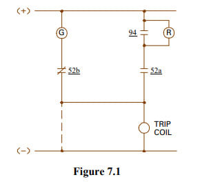
Hello World! I'm trying to get an understanding of an actual product to use for the Red lamp in Figure 7.1. The figure came from a relay trip circuit design pdf. [] The document describes the red lamp as a 24V, I think incandescent, bulb with a series resistance. Is there a rule of thumb for the series resistance that's used here to ensure the lamp lights but the coil doesn't trip? Is there an industry defacto standard light that exists with an integrated resistance?

It also suggests that LED lamps can be used but it needs to be designed to have sufficient draw to not light under a high resistance such as a burned-open trip coil. What do they mean by sufficient draw? Are there standard COTS light assemblies used for this purpose or is it just any old panel indicator with some resistance added to it?

2023-08-10_15-15-18_zxafij.jpg


Thanks,
David
 
Replies continue below

Recommended for you

I think the right way would be to compare your trip coil resistance with the light resistance and make sure the light resistance is much less than the coil resistance ( coil voltage ends up being well below tripping minimum voltage) Realistically I’ve just seen standard red panel lights or LEDs used.

Your schematic is a little odd though, I’ve never seen the green light wired through the trip coil in any of our switchgear or HV breakers.
 
The good old red & green lamps are famous for burning out, or burning out right when you need them.

TCM monitoring can be implemented in most digital relays. 2 Inputs are needed, as well as a little logic. Input #1 is 52a, which is likely used already as well as Input #2 which is in parallel with the trip contacts. Logic is simple In1 & In2 = 0 OK, In1 &IN2 = 1 = OK. If In1 1 and In 0, or reverse and there is a problem. Most add a small time delay to declare a problem.
 
The use of LEDs helps with the burned out issue. But the light needs to use a few ma of current to light, where the trip coil needs a few amps to trip, so the resistance is just a voltage divider to lower the voltage to the light.
But is you use a trip coil monitor, and a red light, be careful as most simplified schematics will not show all of the circuit and you can get some interaction between the red LED and the trip coil monitor.
Use a commercial product and don't try to design the whole light your self.
 
Per your drawing:

The common practice was to have a sizable resistance as part of the lamp assemble so that shorting the lamp itself or its socket would not result in a trip of the circuit breaker.

I can't remember ever seeing the green light wired through the trip coil.

old field guy
 
Wiring the green light through the trip coil is not very common, but it is the only way you can tell if you have a trip coil prior to closing your breaker.
That said if you use a trip coil monitor, add a small delay as when you activate the trip coil, your trip coil monitor will be blinded, and can give a false indication.
Nothing like a dispatcher tell you the trip coil failed when he issued a open. So he is not going to put the breaker back in service until a maintenance person has looked at it.
 
I'd echo cranky108's comments, use a product designed for the function. I've seen people try and save money on this and it come back to bite them. Another example I can remember is back emf from the trip coil damaging the coils they installed for TCS.

As thermionic1 said, most of the numerical relay's opto inputs are good for this function, but worth checking that there isn't procedures in place that say something like "rack the breaker into position and confirm the LED/Lamp turns on".

Speaking from my own personal experience, your fully functioning TCS scheme may still create an issue for the operators !
 
Status
Not open for further replies.
Back
Top