Continue to Site

Eng-Tips is the largest engineering community on the Internet

Intelligent Work Forums for Engineering Professionals

  • Congratulations GregLocock on being selected by the Eng-Tips community for having the most helpful posts in the forums last week. Way to Go!

Prototype Fuel Injection - How Much Fuel Can Air Hold? 4

Status
Not open for further replies.

RodRico

Automotive
Apr 25, 2016
508
Guys,

My prototype engine is 49.5cc but, since it has six cylinders and each completes four full cycles per revolution, each cylinder volume is only 1.7cc. There's only 2.76E-6 kg of air mass in the cylinder and the stoichiometric ratio for diesel is 14.7, so there's only 1.88E-7 kg or 0.0002 cc of fuel required. There's no feasible way to atomize that little fuel... the nozzle orifice and tolerances required by a classic fuel injector design are simply unrealistic.

The obvious solutions are to either build a much larger engine or use a shared intake manifold with a single injector or carburetor. Neither approach is attractive... the larger engine would be costly to build and too big to allow shipment of an engine and test bench to third party evaluators, and the shared intake manifold would require I segregate intake and scavenge air paths which significantly increases complexity.

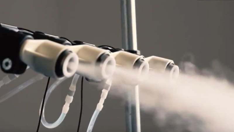
My current thought is to use a shared manifold to route premixed fuel/air to a simple injector. This is essentially a way to segregate intake and scavenge without adding a lot of complexity. To be feasible, the fuel/air mix must be *very* rich to allow use of a small injector similar to what I had envisioned. I did some research and found the easiest way to make a dense mist with small droplets is using a piezoelectric atomizer, preferably one using a piezo mesh disk as these produce very small droplets. This $20 mesh disk produces 8um droplets at 480cc/hr versus my whole-engine peak requirement of 812 cc/hr, so two such devices should do the job. The output of these devices can be electronically controlled (droplet size is determined by the driving signal's frequency and the density by it's amplitude), so there's no need to control the injector at the cylinder; it can just be a simple piston with fixed stroke that draws in the charge then shoots it at high velocity into the cylinder to further aid mixing. Here's a picture showing how dense the spray from these type devices is...
Capture_dw1mbs.jpg


My question is this: Does anyone have any idea how much fuel a given volume of air can hold?

Thanks for your help!

Rod
 
Replies continue below

Recommended for you

enginesrus,

My original statement was meant to ask how much evaporated fuel a given volume of air can carry. My intent is to create as rich a mixture as possible then inject it into the cylinder along intake air such that the final mixture is 0.4 x stochiometric. As others have implied in their answers, a fuel spray isn't evaporated, however. I think I'm just looking for the maximum density fuel spray possible.

A carburetor won't work for me. In the current design, the air path is shared by intake and scavenge. With an injector, I can time fuel delivery so none of it makes it out the exhaust ports before they close. I can't imagine how to do that using a carburetor.

The amount of fuel that needs to be injected is so small, it's hard to imagine a classic injector made to tolerances that would be effective. That's why I'm looking to create a dense mix so that the injected volume is larger. I can't make the injected too large, however, or the injector becomes too large.

Rod
 
Then you need to combine heat for evaporation and something similar to the water fogging machines. Oh and don't forget to add me to the patent for my idea's.
 
RodRico said:
The amount of fuel that needs to be injected is so small, it's hard to imagine a classic injector made to tolerances that would be effective. That's why I'm looking to create a dense mix so that the injected volume is larger. I can't make the injected too large, however, or the injector becomes too large.

You keep mentioning that intake and scavenge air share an intake path- is there a diagram in one of your other posts that explains what you're saying? I'm not familiar enough with your design to visualize this.

In any event.. I think with the fuel quantities you're talking about here, it's going to be very very difficult to come up with a cycle-metered solution (like a scaled-down traditional fuel injector). As you already know.

I mentioned the RC stuff because that's at least at the same scale; if I were you, I'd be looking at how a mass-flow metered system could be made to work, at least as a starting point to get the thing producing power on a stand.

Developing an entirely new method of fuel injection on top of all the stuff you're already doing would be quite an additional goal... but based on your past posts that probably doesn't scare you much.
 
jgKRI,

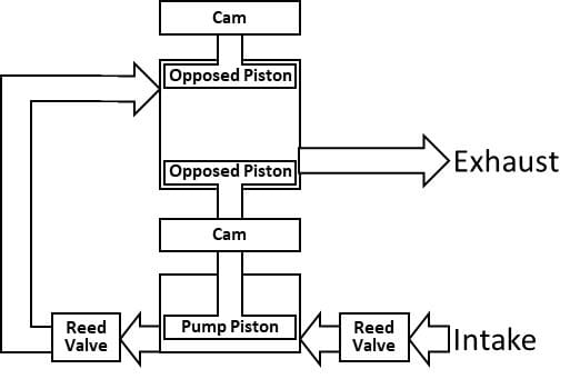
Here's a functional diagram of one cylinder set (of six) in the engine. A pair of opposed pistons share a common cylinder with the upper piston gating the intake ports and the lower piston gating the exhaust ports (uniflow scavenging). A third piston in another cylinder of substantially larger bore pumps air into the intake port. The pump piston's timing is arranged so it is at max volume at the start of the scavenge period. After a bit of time (determined by port flow calculations), the exhaust port closes signaling the end of the scavenge period. The pump piston continues its stroke to complete the intake period, reaching its min volume just as the intake port closes.
Picture1_evx9kb.jpg

From the above, it's clear that an injection system is required to ensure no fuel is passed out the exhaust port. Use of a carburetor would require that scavenge and intake be segregated, and that can't be done without introducing a number of other challenges.

The most complex possible path I'm pursuing is a scaled down version of a classic fuel injector of the unit type; one cam surface driving the piston generating pressure while another controls the pressure bypass valve. This approach requires very fine tolerances and will likely be vulnerable to clogging due to the very small orifice required. In spite of the challenge, I'm currently running CFD on a version of this nozzle scaled down to a .0023" orifice assuming the Swiss Jewel Co. can make the precision parts affordably. Note this injector will have to use pressure multiplying pistons in order to operate with a piston stroke large enough to be feasible within tolerances.

The rich mixture approach (in which a very rich mixture from a common manifold is injected into the cylinder where it mixes with the larger volume of air to yield the final mixture) should be much simpler to construct, but I'm finding it harder to quantify the design criteria.

Rod

P.S. All of this scares me. I just don't let my fear dictate my actions when working with something that's possible but outside the bounds of my current knowledge or skills. I simply learn what's needed and press on.
 
So your plan is a direct injection scheme using this newly designed injector??

Ultimately I'm not an expert in fuel injector design so I don't really have much to add on that front.

I guess the approach I was envisioning was what I would do in your shoes- which is prioritizing getting the thing running and producing power, as opposed to getting every detail correct on the first try.

That is, of course, just a difference in approach.
 
jgKRI,

I appreciate and share your sentiment about getting things working with minimum fuss.

My grand plan is to get the engine working with performance sufficient to attract outside investment. This requires the prototype be close to the desired end-state in terms of architecture (functional block diagram).

If there were a way to use a carburetor that didn't differ significantly from the desired end-state, I would gladly go that route. It does me no good, however, to prototype something that isn't representative of the end-state. Since segregation of intake and scavenge air flows adds a lot of complexity, it's not representative, so I'm not comfortable taking that path.

I believe I'm stuck with some form of injection whether it be a classic fuel injector or the alternate approach which I'll call a charge injector. If the volume of air included in the charge of the second approach is similar to the full intake volume, then the charge injector is really just a segregated intake path, and it would be too large. If, however, I could make the injected charge very rich, the volume of the injected charge would allow use of a small injector piston.

I'm only running the CFD on the classic injector with the sapphire 0.0023" orifice because my engine design consultant suggested I do so before rejecting the option. He feels, with the extreme precision assemblies made by Swiss Jewel Co, the remaining assemblies can be built with attainable tolerances. His approach employs pressure multiplying pistons so that the stroke of the injector and pressure relieve valves can be large.

Rod
 
I guess I still don't understand where this:

RodRico said:
Since segregation of intake and scavenge air flows adds a lot of complexity

Comes from. Intake air is scavenge air and scavenge air is intake air, unless you think that injecting fuel anywhere other than direct injection into the combustion volume somehow means you have to evacuate the cylinder volume twice.

Is your plan to spray fuel directly into the combustion volume, after the exhaust valve is closed, using this jewel orifice injector?
 
If the pump piston's intake is drawn from a manifold with a carburetor, then fuel will be passed out the exhaust during scavenge. Preventing this would require two pump pistons (one for scavenge and another for intake), and that would add a lot of complexity. Even then, fuel would wet the walls of the passage from the pump piston to the intake port on the opposed pistons resulting in fuel in the scavenge air, so the engine would need separate channels for scavenge and intake. This approach is infeasible given the fact that scavenge and intake have different timing and there's limited real estate for separate pistons and channels to the intake ports.

I do plan to inject directly into the cylinder. This gives the most room for mixing to occur without wetting the walls and ensures there's no fuel on the intake passage walls that would subsequently be passed out the exhaust during the subsequent scavenge cycle. I'm even considering injecting just below the intake ports so injection can occur after the intake port closes. This would have the benefit of recovering the work from pressurizing the fuel (and wouldn't subject the injector tip to harsh exhaust gasses as the intake port doesn't open until the exhaust port is open long enough for pressure to settle near ambient).
 
Agree entirely with jgKRI. There are a multitude of hurdles to overcome with your design. Put a carburettor on it and get it running. Who cares if the prototype scavenges a bit of fuel out the exhaust? You will be able to recognise and start addressing the REAL issues with your engine. Fuel metering can wait.

je suis charlie
 
Less cylinders will make your injectors easier to source.
Take a look at the Detroit 51 series. You don't need two pistons to port both intake and exhaust.
These engines were noted for good fuel efficiency and light weight.
One rotary blower has a lot of advantages over six piston pumps.
1.8 L with 50s era mechanical injectors.
Run the numbers on a similar design scaled down to 49 cc.
Link

Bill
--------------------
"Why not the best?"
Jimmy Carter
 
Bill,

Yes, larger injectors would be easier. I believe I've said as much.

The Detroit diesel isn't even close to what I'm shooting for in terms of performance.

Yes, one rotary blower is simpler. It is not, however, as efficient as pushing air only when it is needed as I do. I've run thermodynamic models on both. Properly timed pistons win hands down.

I'm sure if you fully understood what I'm doing you wouldn't be recommending I look to 1951 for the answers. There is nothing predating the turn of the century that even comes close to what I'm trying to achieve. Granted, I may (or even be likely to) fail, but I'll not be wasting my time building what's already been proven not to meet today's needs.

Rod
 
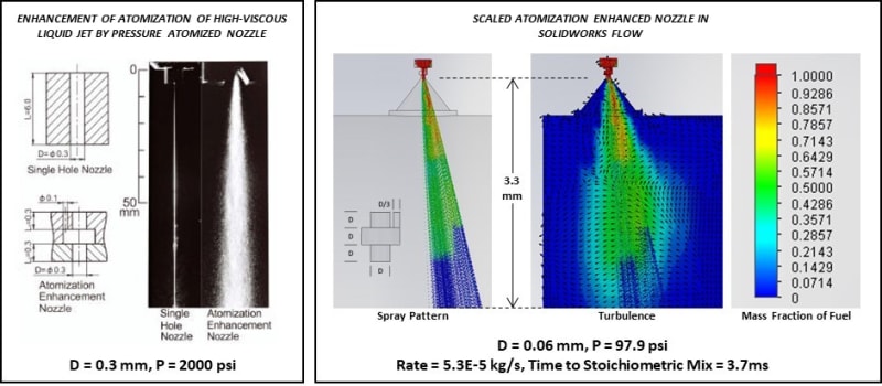
Here's a look at the nozzle for a micro fuel injector using Solidworks flow simulation. The colors are mass fraction of fuel; red is 100% fuel while dark blue is 100% air. For this simulation, I used ethanol rather than diesel because the Solidworks liquid library already had a full definition of ethanol characteristics over temperature and its density is close to diesel (at some point, I'll need to build a library entry for diesel).

The nozzle geometry is scaled from that presented in the paper "Enhancement of Atomization of High-Viscous Liquid Jet by Pressure Atomized Nozzle" using sapphire orifices such as those from the Swiss Jewel Co.. The spray pattern developed using Solidworks looks quite similar to that shown in the paper, but is also scaled. It's tilted a bit due to the proximity to the wall formed by the piston face and appears to break up to zero fuel fraction in only 3.3 mm. The pressure is only about 100 psi to deliver 5.3E-5 kg/s fuel and, at this rate, the entire charge raises to stoichiometric in only 3.7 ms.

The micro injector will obviously need a good fuel filter. I think it would simply be a screen (to catch large particles) followed by a comparatively large disk of sapphire with many holes of the same diameter as the orifice (0.06mm). I'll be calling the folks as Swiss Jewel to find out what they would charge to make these assemblies in small quantities. If the price isn't too crazy, I'll then proceed to design the full injector around the nozzle.

Fuel_Inject_2_d6wqid.jpg
 
Rod,

I don't know all the details about your injector geometry but just looking at the orifice diameter you are trying to achieve (0.06mm) and the fact you might want arrays of these holes it seems you are starting to get down into MEMS territory. MEMS foundries can work with sapphire wafers and can etch very fine features so you might want to start researching MEMS and the deep reactive ion etch (DRIE) process that can create higher aspect ratio holes that I think you might need. Be warned though, this isn't a cheap process, especially with sapphire substrates.
 
hendersdc,

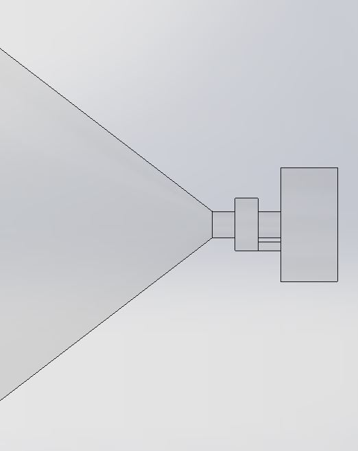
The nozzle as simulated is comprised of three disks. The lower disk with the cone is off the shelf at . The middle disk creates the auxillary chamber, and the last disk has two holes. The middle and last disks are similar to those shown at For all I know, they make these using a MEMS process and if that's the case, I would hope they could run a few customs on part of a shared wafer. In any case, if they want too much for the three disks, I'll explore using one of the many micro-machining shops. The one at offers suitable preceision using wire EDM, for example. There's really no need for sapphire in the prototype and, given the low pressure required, perhaps not even in a production product.

Rod

Capture_bcti2n.jpg
 
I stand corrected.
Thank you for your courteous reply.
Others may not have been as patient nor as polite.
Good luck with your design.

Bill
--------------------
"Why not the best?"
Jimmy Carter
 
Bill,

Thanks for your best wishes! If you have any spare prayers, wood to knock on, etc. I'd appreciate their use as well; I'm going to need as much luck as anyone has a right to expect if this is to work before I die.

Rod

P.S. I'm actually pretty proud of all the work I put into those air pump pistons. The run on the same cam as the expansion piston of the *next* cylinder in the radial set. This required I coordinate the timing of the expansion stroke on one piston with the scavenge and intake period of the next cylinder. Given the many constraints already imposed on the cams, adding the timing requirement really complicated things. I ultimately wrote some VBA in Excel to iterate the cam design until all constraints were met. In the end, the scavenge and intake charge aren't really presurized much (intake is only at 1.45 bar regardless of altitude), so the air pump isn't creating pressure so much as simply moving air when it's needed. All this means there isn't much work going into moving the scavenge and intake charge. The air pump piston, cylinder, and rings are all Vespel with no lubrication required, by the way.
 
The better printer inkjet nozzles disperse 10 micron droplets so do your calculation on that number. I am hoping to put together a list of inline four cylinder diesels that are relatively easy to turbo. In that process, I hope to learn what the typical CFM to HP ratio is, what the optimal boost pressure is likely to be, what the practical rpm limit of a diesel engine is and what strategies to use in raising that number.
 
gmaslin,

Thanks for the pointer regarding droplet size.

The information you seek on diesel turbos is too general IMHO. The "optimal boost pressure" would vary depending on your objective; you might boost only enough to ensure 100% volumetric efficiency or you might boost to the limit of the structural integrity. The typical "CFM to HP ratio" is pretty straightforward once you know the boost pressure and charge temperature after the intercooler; assuming a constant air/fuel ratio (which demands the injectors be cable of the higher flow required with boost applied), it's just a matter of calculating the mass of the air in the cylinder with the boost in place versus that present when no boost is applied. The practical RPM limit is definded by component strength versus reciprocating forces and fuel injector performance. You may be able to find information on fuel injector speed/performance, but it's going to be very hard to determine the structural limit of a given engine without knowledge of the detailed design and materials employed. Modern engines are the product of thousands of hours of engineering, and messing with the design without all the required information and tools is fraught with risk.

Rod
 
mighoser,

I’d be surprised if a polymer was strong enough for a traditional injector operating at thousands of psi. Besides the pressure, cavitation erosion is a big deal. Bird makes ruby jewels with 0.001” orifices, and they’re the basis of my current approach.

The polymers might be handy in other ways. Thanks for the info!

Rod
 
Status
Not open for further replies.

Part and Inventory Search

Sponsor