Eng-Tips is the largest engineering community on the Internet

Intelligent Work Forums for Engineering Professionals

Prying Action - Floorbeam to Girder Double Angle Connection

Status
Not open for further replies.

CalebA

Structural
Apr 3, 2023
21
0
0
US
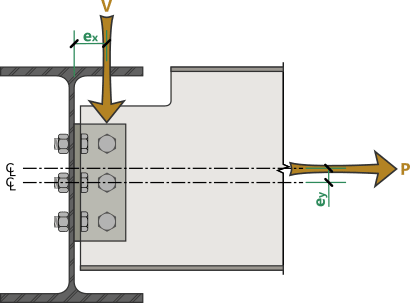
I am designing a double angle connection between a floorbeam and a girder web on a bridge. The floorbeam is coped, has a 6.5" eccentricity to 15 bolts 3/4" A992 bolts spaced at 3", and has a load of 308 kips at the girder. I am having some trouble coming up with the required strength, T. Can I extrapolate T from the moment created by the eccentric point load? Would I even need to account for the prying action in this case?
 
Replies continue below

Recommended for you

Is this a single or double column of bolts? Look at the AISC design examples and it will show you how to analyze the connection.

Also note bolts are not A992, they are A325/F1554 or A490 (not sure off the top of my head the F designation). Make sure you are using the appropriate allowable stress for your bolts based on the selected grade.
 
Not sure which bolts you are talking about, but if these are the bolts connecting to the actual web of the girder, they are designed for shear only (assuming pinned connection).

Remember to check the moment at the end of the cope.
 
This is just a single row of 11 A325 bolts. I am talking about the bolts between the column and the angles. I was failing for prying in the angle > I upped the angle size > then I was failing for rotational ductility > I ended up eliminating the eccentricity by removing part of the existing structure. I got T from the following equation that RISA Connection uses, but I'm not sure where it's found in AISC: Me = V*ex + P*ey & Tbolt = (6Me/(b*d^2))*At*keff & T = Tbolt + P/(n*b).
 
If you check out the "General Reference" document for RISAConnection, it says:

RISAConnection General Reference said:
Worst Case Bolt Tension
The procedure for calculating the worst case bolt tension caused by moment due to eccentricity is borrowed from Steel Structures: Design and Behavior, 3rd Edition by Salmon and Johnson. In this procedure, the bolt tension due to moment is added to the bolt tension caused by a pure axial force to come up with a total required force.

To calculate the axial load due to moment, we assume that the plate or clip angle acts as a solid rectangular beam in flexure. The flexural stress at the bolt row furthest from the center is then multiplied by the tributary area of the bolt (At).

Coefficient Correction Factor, k_eff
Because our bolts do not connect to the extreme fiber of the connecting plate or clip angle, we use the k_eff coefficient to scale back the calculated value of Tbolt to be exactly that at the location of the bolt.

That's where Tbolt = (6Me/(b*d^2))*At*keff comes from. (Refer to "Steel Structures - Design and Behavior" by Salmon and Johnson for a full explanation.)

Me = V*ex + P*ey is just the moment due to the eccentricity of the shear and axial loads (see graphic below).

Beam_to_Girder_Connection_Eccentricity_i5kd9z.png


Finally, T = Tbolt + P/(n*b) is actually T = Tbolt + P/(nb), where nb is one variable for the number of bolts, so they are just combining Tbolt (which was determined above) with the tension in the member divided evenly amongst all of the bolts.

Structural Engineering Software: Structural Engineering Videos:
 
Status
Not open for further replies.
Back
Top