Continue to Site

Eng-Tips is the largest engineering community on the Internet

Intelligent Work Forums for Engineering Professionals

  • Congratulations SSS148 on being selected by the Eng-Tips community for having the most helpful posts in the forums last week. Way to Go!

Prying action on beam clamp

Status
Not open for further replies.

TEDstruc

Civil/Environmental
Dec 6, 2017
43
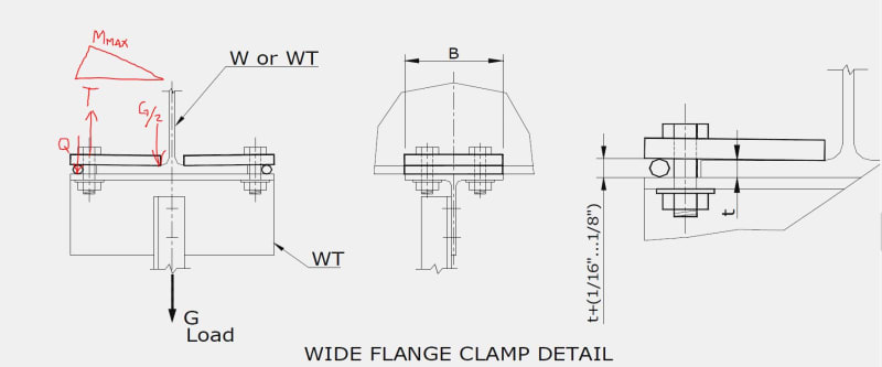
Does anyone have any experience calculating prying action on beam clamps, such as the below example? In this case assume the flange of the WT below is stiff enough to prevent prying. Could you provide some guidance on how to determine prying force to add to initial bolt tension? I'm assuming prying force will be applied at the round bar, but would appreciate any guidance for this somewhat unique situation. These clamps are commonly used in car plants.

The formula for the typical scenario with a WT or pair of angles bolted to a hanger don't seem to cover this scenario.

Thanks in advance.

Capture_gouoy0.jpg
 
Replies continue below

Recommended for you

For that exact example... the spacer wire is so close in thickness to the flange, and so much less stiff in compression, I'm not sure there actually would be any prying action. The bolt, unless it's tiny, can probably provide enough force to deform that wire until it is the same thickness as the flange on the other side and the forces wind up relatively balanced.

For less-perfect examples, when I've had to check this I use the same formulas as for the common WT example, except you can neglect the component from externally applied tension since the load is reversed.

This is all just conjecture/what I happen to be personally comfortable with.. I know of no example from code or any other trustworthy source which addresses an example like this.
 
jgKRI,

Thanks for your reply. There's probably a more detailed analysis that could be done by looking at the relative stiffness of the various components, but I was hoping to avoid going that route. I saw an analysis of a similar clamp by another engineer who added 60% of the externally applied load as a prying force. I think they did this based on a provision in ASD 9th edition manual, Appendix K, for tensile fatigue of bolts, that states for bolts subject to prying forces, the prying force shall not be more than 60% of the externally applied force. I don't think this approach is appropriate. You could have no prying force or even a prying force greater than 60% depending on the geometry and stiffness of the parts. Anyway, I was hoping to come up with a way to a) check for prying, and b) calculate the prying force for this scenario.

The main reason I think the traditional formulas don't work here: In the WT hanger example, you have fixity at the intersection of the flange and stem. And an assumption is made that the moment at the flange/stem intersection is approximately equal to the moment at location of the bolt. In my example, the moment at the toe of the clamp is zero, therefore not equal to the moment at the location of the bolt.

Also, as you tension the bolt, trying to compress the round bar, would you be introducing prying at the round bar until the clamp plant is flush with the beam flange? There would probably be some combination of deflection of the clamp plate and compression of the round bar to achieve that state.
 
TEDStruc said:
Also, as you tension the bolt, trying to compress the round bar, would you be introducing prying at the round bar until the clamp plant is flush with the beam flange? There would probably be some combination of deflection of the clamp plate and compression of the round bar to achieve that state.

Yes, but then the load on the widget being hung by the beam clamp applies load on the flange side only, which balances against the prying generated by the round bar in compression. That's what I was referring to when I said "neglect the component from externally applied tension since the load is reversed".

 
Status
Not open for further replies.

Part and Inventory Search

Sponsor