Continue to Site

Eng-Tips is the largest engineering community on the Internet

Intelligent Work Forums for Engineering Professionals

  • Congratulations KootK on being selected by the Eng-Tips community for having the most helpful posts in the forums last week. Way to Go!

Prying action - single bolt and coach screw

Status
Not open for further replies.

kauri

Structural
Aug 13, 2018
36
Hi,

I have a case where the builder has constructed the connection as shown below. In this situation, would the coach screw act as a second bolt with regards to plying forces? Or should I be considering this a single bolt connection? If the latter is the case, how should one go about calculating this?
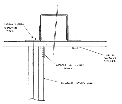
Capture_trbdu1.png


Thanks in advance :)
 
Replies continue below

Recommended for you

Loads and direction of loads might help understand the concern better?
 
Why wouldn’t that bolt/screw see any forces? Something will get transferred there.
 
Whoopdedo_LSU said:
Why wouldn’t that bolt/screw see any forces? Something will get transferred there.
I agree - the coach screw will have some shear and uplift capacity, which you can calculate. It most definitely won't be as much as the M12 bolt, but you can make an assessment from there as to whether the connection is still adequate or not.

 
Sorry, maybe I should have made it clearer that I'm talking about prying forces. Ie flexing of the angle bracket, reducing contact pressure of the bracket and top plate, developing a force at the edge of the bracket. This is added to the tension load on the bolt/screw.

My country's standards I use mentions this a few times, but doesn't explain how to calculate them. In any case, I found a good youtube video that explains it :)
 
well prying forces are not so easy to calculate ...
need to look at load path and deformations and stiffness......
 
I assume a coach screw is a "lag screw" It probably does not have much capacity going thru the interface between two studs.
 
To develop prying action, you also need a sufficiently "hard" bearing surface so the angle legs can bear on and yield... are you sure you can get this with a wood bearing surface? For connections like this I don't consider prying and just check the angle leg yielding.
 
Prying also only develops if there is a force component parallel to the axis of the fastener and in the correct direction.

If this fastener sees only shear load, for example, there is no prying.

So, in short, we can't help you answer your question without knowing the loads.
 
XR250 said:
I assume a coach screw is a "lag screw" It probably does not have much capacity going thru the interface between two studs.
Hopefully the coach screw is not going thru the interface between the two studs - I'll make sure to double check when I'm back on site, thankyou.

T_Bat said:
To develop prying action, you also need a sufficiently "hard" bearing surface so the angle legs can bear on and yield... are you sure you can get this with a wood bearing surface? For connections like this I don't consider prying and just check the angle leg yielding.
I've already checked the angle leg yielding. I hadn't considered the bearing strength of the angle legs - thankyou.

jgKRI said:
Prying also only develops if there is a force component parallel to the axis of the fastener and in the correct direction.

If this fastener sees only shear load, for example, there is no prying.

So, in short, we can't help you answer your question without knowing the loads.
Loads are upwards, 6.2kN on the SHS. I wasn't aware there was any other direction the loading can result in prying forces.


To clarify my question, prying forces typically seem to be dealt with when both fasteners are bolts. Does the fact that it's a coach screw change the fact the prying forces? If so, how?

Thanks guys :)
 
No, and as indicated by others, prying wouldn't be a concern for a few reasons in this instance. Firstly, you have a connection on either side of the SHS and therefore the one bolt would be in pure tension before prying action on the other side began. Secondly, for prying action to occur, you end up requiring something really strong in bearing below otherwise the small bit of angle will just deform the base material and negate any prying action.

But let's say for the sake of argument instead of bolting/screwing to wood base members, you had concrete. I still would argue that this configuration still would not result in prying action.

I am assuming that the 6 kN load you mention is parallel to the wood wall as opposed to perpendicular.
 
I'd check that top plate in bending as well, 6kN is considerably more than the usual NZS3604 load considered on top plates (not aligned with studs) from memory (I'm assuming you are in NZ, based on the sketch and your username). Otherwise throw another stud under the other side. For a load path directly into the studs you can align a gib handibrac and bolt through the top plate as an alternative.
 
Agent666 said:
I'd check that top plate in bending as well, 6kN is considerably more than the usual NZS3604 load considered on top plates (not aligned with studs) from memory (I'm assuming you are in NZ, based on the sketch and your username). Otherwise throw another stud under the other side. For a load path directly into the studs you can align a gib handibrac and bolt through the top plate as an alternative.
Wow! What part of the drawing gave NZ away?

Top plate should have already been checked in the original design, double checked it now and its OK. Thankyou though :)

 
Status
Not open for further replies.

Part and Inventory Search

Sponsor