Eng-Tips is the largest engineering community on the Internet

Intelligent Work Forums for Engineering Professionals

Prying with two flexible members 9

Status
Not open for further replies.

TEDstruc

Civil/Environmental
Dec 6, 2017
43
0
0
US
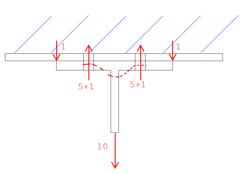
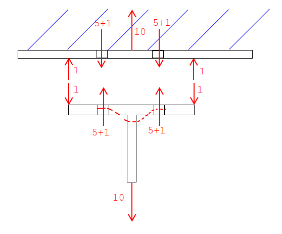
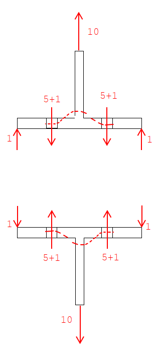
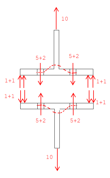
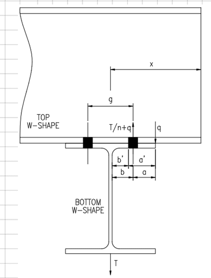
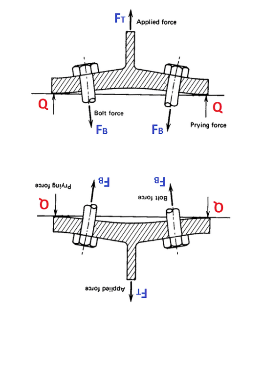
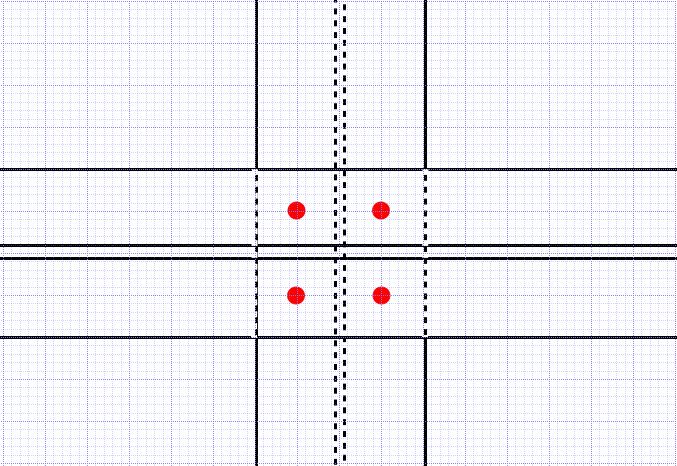
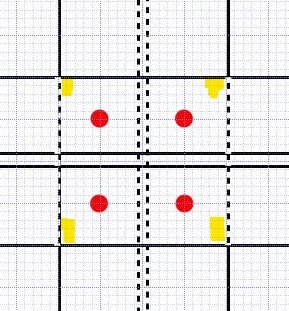
Lets say you have two intersecting beams bolted flange to flange, where the upper beam is supporting the lower beam. You check prying for both beams, and both have resulting prying forces due to their thin flanges... Would the prying forces for both beams be additive to bolt tension? Or would just the worst case prying force be added to bolt tension?
Capture_eaem7w.png
 
Replies continue below

Recommended for you

I don't really understand where the prying would develop in reality in this connection. It appears to be straight tension transfer. If the flange was so thin that it's going to bend enough to generate prying, you've chosen the wrong beam.
 
The upper beam flange does not experience prying. If it were infinitely stiff, the suspended beam flange would feel maximum prying. It the upper beam flange deflects as a result of the upward force of the flange tips of the suspended beam, then prying of the lower beam flange is partially relieved. As a result, flexibility of the upper beam flange would partially relieve bolt tension.

That was incorrect. There is prying for both flanges. But are they additive?
 
If I'm understanding the connection, the forces only become additive after the preload of the bolt has been reached, and the prying would be the result of a moment applied.

-----*****-----
So strange to see the singularity approaching while the entire planet is rapidly turning into a hellscape. -John Coates

-Dik
 
Wow, very thankful for the responses, I do appreciate the input. It's seems there are a wide variety of opinions on the matter.

Maybe I can simplify this question. Let's assume there's no moment being transferred. Both beams are the same size and have the same bolt gage. I want to calculate an absolute connection capacity based on bolt tension considering prying effects. Are the prying forces of the lower and upper beam flanges additive? Another way to look at this might be if the lower beam were a WT cut from the same beam size as the W-Shape above...

For both beams, you are transferring bolt tension thru the flange. If the flange is thin enough, prying will be induced. I don't see any reason there would be prying from the bottom beam, but would not be prying from the top beam. If this logic is flawed, please explain.

Thanks guys
 
jayrod said:
I don't really understand where the prying would develop in reality in this connection. It appears to be straight tension transfer. If the flange was so thin that it's going to bend enough to generate prying, you've chosen the wrong beam.

Well, this is no different than the classic T-hanger example for prying that was used to teach it for years. Now, your solution is a good one. If prying is going to be an issue, then it would be easiest to just use members with a thicker flange. In fact, with most cases where prying could be a problem, I always want to thing about increasing the thickness.

To me, this thread is more of a question of what do you do when you are presented with an situation where the members are not thick enough to avoid prying.

I have a hard time believing the prying forces would be additive. Where are they coming from. If one flange bends a certain about, it's pushing on the other flange which creates the prying action. The idea that this force will be additive if they both bend flanges is silly to me. It's the same force. You shouldn't apply it twice. Tell me why Q in the image below is different if you only have prying on one side? Certainly calculate prying for both flange, but the one that controls is the larger one, not the addition of the two.

double_prying_u6ylmf.png
 
I agree the bolt forces would not be additive. For reasons largely already explained.

The face that the prying forces are orthogonal don't change the axial forces through the bolt which are not orthogonal.

Elongation shouldn't change things. The forces still resolves satisfactory if the load is calculated from the greater prying force.

(Though of course I could be wrong, some quite astute engineers here have a different opinion.)
 
I still think it is additive. The additional force in each bolt is due to the "Q" force caused by prying. There could be two "Q" forces at the bottom flange of the upper beam, and two different "Q" forces at the top flange of the lower beam.

All that being said, I don't think it matters. I reviewed AISC prying force design, and it is focused on the bending stress in the flanges, not the additional force in the bolts. The force in the bolt is automatically acceptable if you follow the procedure.

DaveAtkins
 
DaveAtkins said:
I still think it is additive. The additional force in each bolt is due to the "Q" force caused by prying. There could be two "Q" forces at the bottom flange of the upper beam, and two different "Q" forces at the top flange of the lower beam.

Not for the "one way" prying that I showed in my picture. The Q force is the same. One flange pushes against the other flange with the force Q, that flange pushes back with the same force Q. So, for a one way prying action, it is IMPOSSIBLE for the Q forces to be additive. It's just basic statics.

Now, I admit that I hadn't thought of it in a "2 way" prying sense like BA Retired's picture. That makes me less confident in my assertion that the Q forces can't be additive. I still doubt that could be the case, but I'm not as confident as I was when I was thinking of the one way prying.

Note: I'm using one way and two way in a similar sense of how we use those terms for one way or two way shear in slabs. If we're only bending in one direction, the solution is perfectly clear (at least to me). For two way bending, I'm not as confident.
 
JP said:
Where are they coming from.

human909 said:
The face that the prying forces are orthogonal don't change the axial forces through the bolt which are not orthogonal.

This is where the extra force comes from and it's precisely because the two prying mechanisms involved are orthogonal:

DaveAtkins said:
There could be two "Q" forces at the bottom flange of the upper beam, and two different "Q" forces at the top flange of the lower beam.

In this situation, you've got two "Q" forces that need to be reacted by each bolt instead of the usual, single force.

Don't make me waste a billable hour on a damn 3D sketch...
 
If both flanges would be considered flexible, would the upper flange not bend such that the two surfaces remain mated and therefore no prying occurs?

The tension in the bolts would pull down on the center part of the upper flange, and the resulting Q force would attempt to bend the upper flange outside of the bolts upward, forcing the upper flange to deflect in the same way as the lower flange, not in opposing ways. Maybe I'm missing something but in my head the two surfaces remain mated fully. At a minimum, due to this flexibility of the upper flange, I wouldn't think they're additive as there is only one force creating the entire scenario. Similar to a tension tie between two moment frame column bases. You don't add the two reactions, one cancels the other out.

Edit: perhaps I've figured out why my scenario wouldn't happen, the orthogonal orientations would have the webs acting as stiffeners preventing the mating I was describing. If there were stiffeners added in the other directions to both the upper and lower beams, does the prying become eliminated as now you'd have two stiff plates connected to each other?
 
In reality there probably would be some degree of resistance offered by the combined thickness of the two flanges involved......but I personally would just check them individually. (With that load "T".)
 
Prying_Plan_dxufsl.jpg


I have been thinking more about this. I believe what happens is you end up with four "Q" forces as shown highlighted on the sketch above. But I still say it doesn't matter if you follow the AISC design procedure.

DaveAtkins
 
...and what is the impact if you add stiffener plates to the beams?

-----*****-----
So strange to see the singularity approaching while the entire planet is rapidly turning into a hellscape. -John Coates

-Dik
 
KootK said:
This is where the extra force comes from and it's precisely because the two prying mechanisms involved are orthogonal:
Except if you are separating the two prying mechanisms into orthogonal systems and then adding them, then you need to separate the force proportionally. EG;
0.5F for one T stub
0.5F for the other T stub
(The proportion 0.5 of course depends on relative behaviours of the two T-stubs)

So when you sum the orthogonal systems again you don't suddenly end up with 2F.

KootK said:
Don't make me waste a billable hour on a damn 3D sketch...
[tiphat]

DaveAtkins said:
I have been thinking more about this. I believe what happens is you end up with four "Q" forces as shown highlighted on the sketch above. But I still say it doesn't matter if you follow the AISC design procedure.
Agreed.

And your sketch shows the fulcrum moving to a point that is further away, so potentially reducing forces. It all becomes 3D and quickly moves away from a simple T stub analysis but I agree that the prying forces are quite unlikely to be more severe and are not additive.


IdeaStatic could likely do this pretty quickly. I don't have access to it at present. So I have to resort to logic rather than pretty computer analysis.

dik said:
...and what is the impact if you add stiffener plates to the beams?
I'm not sure if that is rhetorical or not. The more you stiffen the flanges up the lower the prying forces. The cantilever all but disappears so expect very low prying action almost negligible prying action.
 
Here's how I'm looking at this... I'm going to break it down into steps...
first lets look at the basic tee condition presented in AISC (assumes the tee is prying against a rigid wall or member...)
rigid_kctmbk.png

Every force has to have an equal and opposite reaction for equilibrium, so let's break this up into two free body diagrams and look at those...
Rigid_Reactions_cfixtj.png

Now let's look at the condition with two equal size tees separately...
separate_tees_qjcahm.png

Now let's combine them and apply the q reactions to each opposite member...
tees_combined_klfk6s.png


This is my argument for saying that the prying forces are additive... I would love someone to model this somehow and prove me wrong.
one hang up I have with the argument that the prying forces aren't additive is the case where you have different prying forces above than below...(two different sized thin flanges)
In this case if you just take the worst case prying forces, where do the other prying forces go? Is the system still in equilibrium?

EDIT - I realize that this one way scenario is different from my original question. This was just easier to illustrate.
 
Status
Not open for further replies.
Back
Top