Eng-Tips is the largest engineering community on the Internet

Intelligent Work Forums for Engineering Professionals

Prying with two flexible members 9

Status
Not open for further replies.

TEDstruc

Civil/Environmental
Dec 6, 2017
43
0
0
US
Lets say you have two intersecting beams bolted flange to flange, where the upper beam is supporting the lower beam. You check prying for both beams, and both have resulting prying forces due to their thin flanges... Would the prying forces for both beams be additive to bolt tension? Or would just the worst case prying force be added to bolt tension?
Capture_eaem7w.png
 
Replies continue below

Recommended for you

So I just ran several scenarios in Risa Connection for a beam to column extended end plate moment connection. Risa checks for prying of the column flange if it is thin and it checks for prying of the end plate if it is thin. If both exhibit prying behavior it takes the worst case prying force of the two. It does not combine the prying forces....

I may have just proved myself wrong.
 
I was just wondering... not rhetorical; I'm preparing a sketch to send in to the CISC to see if they have a methodology to accommodate that. I suspect the prying action will be reduced substantially.

-----*****-----
So strange to see the singularity approaching while the entire planet is rapidly turning into a hellscape. -John Coates

-Dik
 
So I just ran several scenarios in Risa Connection for a beam to column extended end plate moment connection. Risa checks for prying of the column flange if it is thin and it checks for prying of the end plate if it is thin. If both exhibit prying behavior it takes the worst case prying force of the two. It does not combine the prying forces....

Interesting. To go back what I was talking about above...I'd do these one at a time. I've got a spreadsheet that does them via the 13th ed. (I think I've got one that does it by the 9th ed. too.) First I'd do the "Bottom W-Shape", and use the bolt tension + prying action force (called "T+Q" in my spreadsheet) result from the first one to plug into the second one (i.e. the "Top W-Shape").

I guess if the second one has a thin enough flange for prying....the resultant tension force probably would appear to be additive.

A reminder as to why prying action kind of confused me back in college. (A text I have on steel design says not to be surprised if that happens. [smile])
 
I've found the above discussion surprising interesting and controversial given the supposedly simple topic.

I don't think anybody (including myself) has provided a thoroughly convincing analysis at this stage. Plenty of good input though.


I'm keen on looking into this in depth but I'm not free for until the end of the week.
 
"This is my argument for saying that the prying forces are additive." .... surely the picture shows load and reaction ?

I think the two flexible flanges may produce greater prying forces because of the increase in flexibility ... not a flange being pulled away from a rigid plate.
or would it be less ?? (because of the increased flexibility) ...

"Hoffen wir mal, dass alles gut geht !"
General Paulus, Nov 1942, outside Stalingrad after the launch of Operation Uranus.
 
I've run some connection FEA using Ideastatica. The preliminary results from that analysis. On initial inspection I see no major reason to not trust the results from this computer model.

-The forces are near enough to additive. (which wasn't what I initially posted)
-Two beams at 90degrees to each other have slightly lower forces than 2 beams connected parallel to each other (the orthogonal nature of the connection is not highly relevant.) (quick 2nd test shows it depends)

My preliminary conclusion. Two flexible flanges gives twice the flexibility and thus roughly double the prying force as the prying force is dependent on the stiffness of the flange.

I'll follow up with some pretty pictures and some data in the next day or two.
 
TedStruct said:
So I just ran several scenarios in Risa Connection for a beam to column extended end plate moment connection. Risa checks for prying of the column flange if it is thin and it checks for prying of the end plate if it is thin. If both exhibit prying behavior it takes the worst case prying force of the two. It does not combine the prying forces....

RISAConnection does NOT do any type of fancy analysis for prying action. It merely applies the code equations from AISC. I would NOT take what RISA does as any kind of definitive rule on whether these forces would be additive or not. You can verify this by contacting their technical support.... which I predict will have little knowledge about why the program is doing the calculations the way it does. [wink]

Note: I say that because I am a former VP of RISA and was with the company for 16 years. I was the project manager for RISAConnection, I believe, during the time that RISA implemented prying action. At least for the bolted end plate moment connection. But, I believe I also helped guide the implementation of prying for other connections as well. Regardless, my recollection is that the AISC examples on the subject mention how to calculate Q forces, but I don't think they ever talk about them being additive. But, if I remember correctly, they also never had an example where both connection flanges / plates were flexible enough to contribute to prying.

 
I was curious and put a quick model together.
I am finding that these are not additive.

the thin to thin has just a minor amount more tension, small enough I would consider negligible.

Modeled from plate elements
8" wide flanges 14" deep all plates 1/4" thick (except where varied to check thick flanges)
Modeled rigid tension links (bolts) at a 6" gage. All plates on 1"sq mesh
Modeled all other connection interface with rigid compression links.


2500# total load applied (Tried with more load as well all similar results)
thin = 0.25"
thick = 1"

Thin-Thin = 1300# / bolt (around 675 prying)
Thin-thick = 1250#/bolt (around 625 prying)
Thick-Thick = 740#/bolt (around 115 prying)(115# is considered theoretical no prying since this is well beyond thick material limits for 2500#)
AISC 14th checks are coming up around 1240

Understanding that this doesn't fully model the bolt/flange interface,doesn't model the bolt holes. I think it is doing pretty good capturing interface otherwise and aligns with AISC prying check.

I'm going to try to insert the RISA 3d Model and some sketches.

 
 https://files.engineering.com/getfile.aspx?folder=24062e54-f587-472d-ac9c-f5d077727105&file=They_say_Im_pretty_pry.r3d
Thanks Port, did you manage to model the beams parallel as well?
That would really put this to bed.

Kind of surprising to see the AISC calculations so close to the model results.
 
Run both parallel

Thin-Thin =1257/bolt
Thin-Thick = 1253/bolt
Thick-thick = 882/bolt

Interesting that even 1" plate and low forces models out to have some prying, where traditionally its assumed that the prying is negligible.
I have the tension elements (bolts) as perfectly rigid, My guess is that this prying on thick to thick goes down if there is they are allowed some stretch, could be something to play around with. I'm out of time to mess around with it.

One problem brings on another.

I was also shocked the AISC came as close as the model. Nothing works out that nice, It makes me think I've messed something up somewhere.
 
 https://files.engineering.com/getfile.aspx?folder=9af349cc-2d1f-4960-b82c-5db5a0212ae0&file=They_say_Im_pretty_pry.r3d
Portf125 said:
I'm going to try to insert the RISA 3d Model and some sketches.

To my knowledge, RISA-3D does NOT account for non-linear geometric effectst. The exception would be for frame members (that are split into pieces) and when you have requested a P-Delta analysis.

I am pretty confident that RISA does NOT account for P-Delta (or any 2nd order / geometric non-linearity) for plate elements at all. The only exception potentially being for wall panel elements (which are internally built out of plate elements).

Therefore, I don't believe your model actually proves anything. Sorry!


I could be wrong, of course. RISA does seem to have added an option to do geometric modification to the stiffness matrix (which they didn't do back when I was there), though I wrote the specification for how it could be done. However, I believe that this again ONLY applies to frame elements.

Now, for the simple 2D case where you have Tee hanger on both sides... you could model this out of meshed / split frame elements with P-Delta turned on. That would give a pretty good test. In fact, maybe I'll do that this weekend just to prove it to myself.

 
There is so much going on that is difficult to model. For example, how do you account for the pretension in the bolts that essentially clamps everything together?

DaveAtkins
 
Ideastatica Results with some minor commentary

-70x70 square bolt pattern
-Thin = 200UB22 (7mm thick flange)
-Thick = 200UC60 (14.2 thick flange)
-XThick = 200UC60 (custon 40mm thick flange)

Thin-Thin-90deg - 156% (excess prying force of axial load, total bolt load 256% of axial load)
Thin-Thin-0deg - 124%
Thick-Thick-90deg - 16%
Thick-Thick-0deg - 33%
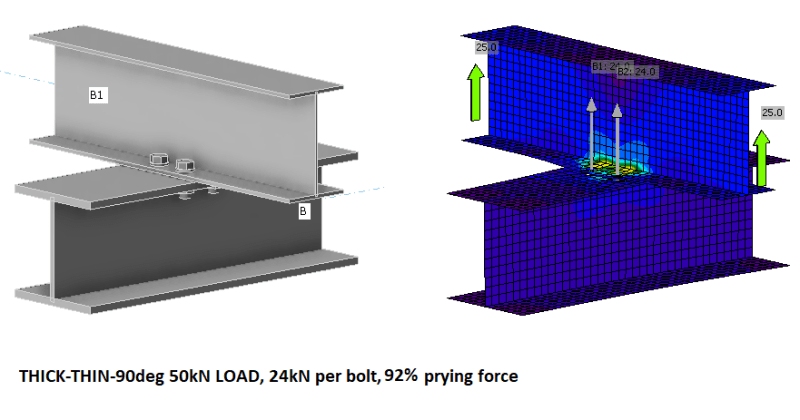
Thick-Thin-90deg - 92%
Thick-Thin-0deg - 90%
XThick-Thin-90deg - 67%
XThick-Thick-90deg - 8%


temp_c07szi.png


Commentary:

Three items to note:
-Prying force is largely independent of magnitude of force while deflections and plastic deformation is low (as one would expect)
-The rotation of the members does not have a consistent effect and can be +ve, or -ve on prying force depending of the magnitude. This behaviour is conjectured to be because of the changing fulcrum point and changing stiffneess having different and opposite effects.
-The prying forces are actually observed to be MORE than double for thinner flanges but double for thick flanges. This is conjectured to be because prying is not linear with stiffness.

Interesting results. If you accept these results without to much doubt on the modelling, then [bowright]congratulations[bowleft] for those who said the forces double. A good learning point for those who had the incorrect answers (MYSELF included).

Regarding the reliability of Ideastatica compared to AISC, refer to the document below:
[URL unfurl="true"]https://assets-us-01.kc-usercontent.com/1ca05609-4ad1-009e-bc40-2e1230b16a75/8fcf6e15-47a1-480e-aecb-50d4b1a0b33d/T-stub-prying_forces.pdf[/url]
The results of the force acting on a bolt including prying force of IDEA StatiCa generally lies between
the analytical approach using geometrical values of a and b and recommended approach using
geometrical values of a’ and b’ in formulas for bolt forces including prying forces. Therefore, the
magnitude of prying forces is slightly overestimated in IDEA (by cca 10 to 15 % compared to
recommended approach), which is conservative.
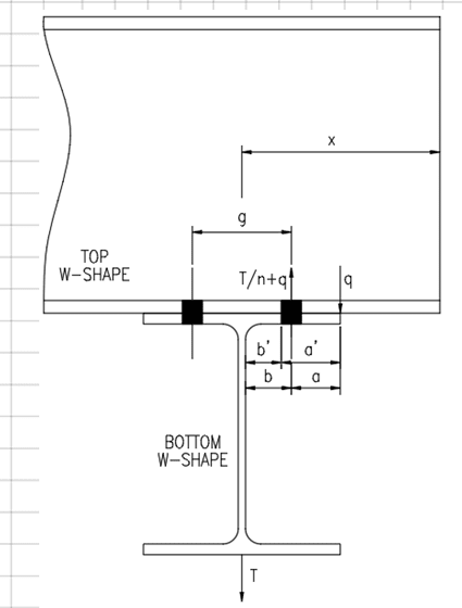
 
DaveAtkins said:
There is so much going on that is difficult to model. For example, how do you account for the pretension in the bolts that essentially clamps everything together?
Very true. Ideastatic isn't bad though, and is well tested, though it still has it's limitations. I don't believe it allows explicitly for preloading. Though turning on friction bolts it reduces the deformation as the bolts take some shear and so the prying forces on thin-thin go from 156% to 108%. (tested just then in response to your post)
 
For the 2D model, I find that it's pretty close to the same force and it is NOT additive. I'm not all that confident that the results will hold for a 3D model. If I'm really interested, then I MIGHT try to model it in SAP2000 and play with that programs non-linear features to see if we can get a more definitive result.

See RISA results below:

I start out with just a 1" thick WT that has an 8 inch wide flange. And, I vary the thickness to 0.5" and 0.25".

Prying_results_RISA_Demo_z5pels.png


I used a 0.75" round for the bolts (two way member) and compression only semi-rigid links for the contact elements. All had moment releases on both sides. But, I put an axially "soft" link member in the center that was fixed at both ends so that the results would be symmetric and we wouldn't get instabilities.

Note: I'm using the Demo version of RISA (version 17) because the model was too large to save.
 
Its curious to me that the results of this doubling aren't easier to recreate.
I wonder if anyone has physically tested this, I imagine there are some results out there from end plate moment test.


Ideastatica looks like a very interesting piece of software.

I will personally be using stiffeners.
 
Stiffeners have limited effectiveness. To get them to work, they have to be close enough to interfere with bolt installation in most applications I've tried.

There's a good article from an AISC practice journal (I think) somewhere. If I weren't on my phone on a Friday night, I'd look it up. I'll try to find it next week.
 
phamENG said:
Stiffeners have limited effectiveness. To get them to work, they have to be close enough to interfere with bolt installation in most applications I've tried.

There's a good article from an AISC practice journal (I think) somewhere. If I weren't on my phone on a Friday night, I'd look it up. I'll try to find it next week
That doesn't make intuitive sense. A stiffener can change the load path from a cantilever flange to a flange supported on two sides, this stiffens things up considerably. A quick check using IDEAstatic shows reduction of prying force from 156% to 80%, almost half the prying force of unstiffened flanges.
 
Status
Not open for further replies.
Back
Top