Continue to Site

Eng-Tips is the largest engineering community on the Internet

Intelligent Work Forums for Engineering Professionals

  • Congratulations KootK on being selected by the Eng-Tips community for having the most helpful posts in the forums last week. Way to Go!

PSV Reaction Forces in a CLOSED System

Status
Not open for further replies.

slhutzley

Mechanical
Dec 8, 2021
7
Is there a reaction forced imposed on PSV inlet/discharge piping in a closed system relieving to a flare header? And should piping and structures be designed to handle that loading in steady state?

I know many companies who do not consider reaction forces on closed systems, and several who consider the transient reaction force applied at the PSV as a steady state. When considering the transient force as a steady state OCC loading (calculated with your preferred method), you are often forced to provide heavily braced structures at the PSV discharge to accommodate the load. Meanwhile, next door is a system designed assuming no reaction, no heavy reroutes or bracing, and I have not heard of these closed system PSV's jumping off of platforms and flying across a refinery.

The argument for no-reaction usually involves the following points:
- the transient force is so short lived, that the piping system cannot physically react to it before steady-state flow is established and loading goes away. I refer to this as the "ball peen hammer" argument. A ping from the hammer that can have local implications if the PSV isn't sized correctly, but otherwise, the whole system does not feel the force. As long as there are no excessively long runs, transient forces are quickly balanced.
- this method has been used for 70+ years, and closed system PSV's do not have common issues. You can stand next to a closed system psv when it pops and not witness a jump. Use an axial restraint near the discharge so that impulse forces have something to bump up against, but do not run the force as steady state.
- the codes usually have a statement saying "closed systems do not impose moments on piping systems" (but is then followed up by "but you should do a transient analysis to confirm").

The argument for applying
- no published transient analysis have been done proving the methods above, so better safe than sorry. Codes usually include an ambiguous statement that leaves room for doubt.
- we don't have the time to do transient analysis, so a conservative approach is to design to a steady state load.
- if the approach is to provide an axial restraint on the discharge, what do we tell CSA to design it to?

Can anybody cite real evidence in favor of either approach? Is there any consensus from the code committees on this? I have talked to different people in the B31.3 committee and they differ in opinion as well. Surely this has been researched and resolved at some level? Any insight is appreciated.
 
Replies continue below

Recommended for you

I can't comment in detail on this, but this extract from API 520 Part II (2020) may answer your concern.

API_520_Part_II_2020_Paragraph_5.8.3_w7sisd.jpg


Note that there is a separate safety relief valve forum on eng-tips.


*** Per ISO-4126, the generic term
'Safety Valve' is used regardless of application or design ***

*** 'Pressure-relief Valve' is the ASME/API used term ***
 
Yes, this is the ambiguity I'm referring to from the code.

This statement seems to imply that loading is small enough to not be considered, except at sudden expansion (presumably at the point where the piping connects to the large volume of the flare header). But then goes on to say, a complex time history analysis is needed to confirm this.
 
Well to be fair to the code writers, they can't take account of all possible permutations - pressure, velocity, sizes, flow rates etc

My take on this is that where you have a liquid system say discharging into a liquid drain line or similar with non flashing liquid then reaction forces are very low.

Where you have gas or flashing liquids where the exit velocity from the relief valve into what is essentially a much larger very low pressure pipe is very high, you have the equivalent of a jet engine putting force on the valve which is being resisted by a mixture of the inlet piping connections and the outlet piping connection to the flare header. Flare header are a bit notorious for being rather thin as there is "no pressure" in them...


Remember - More details = better answers
Also: If you get a response it's polite to respond to it.
 
Jet reaction forces are always considered at relief valve discharge acting horizontally at relief valve outlet towards relief valve even in a closed system. Transient momentum forces at elbows in a closed header system should be checked for high relief rates. These forces are due to flow reaching upstream elbow producing a momentum force before reaching downstream elbow to equalize this force.

For compressible flow under sonic flow the worst-case transient force would be the same force calculated at discharge of vent pipe which includes momentum force at final elbow plus built-up pressure force due to sonic flow conditions. This is because if the flow is so great as to develop sonic flow in the closed header, this sonic flow builds up critical flow pressure inside the header at maximum sonic velocity as it travels down the header to the exit until it reaches the exit and then steady flow commences. Therefore, just like momentum forces at elbows the critical sonic flow pressure force also acts transiently on upstream elbow before it reaches downstream elbow.
 
The key word in API 520 is "usually".

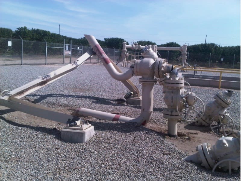
psv_failure_zmvktt.jpg


--Einstein gave the same test to students every year. When asked why he would do something like that, "Because the answers had changed."
 
I was looking for that photo!


Remember - More details = better answers
Also: If you get a response it's polite to respond to it.
 
I know.
Don't lose it this time.

--Einstein gave the same test to students every year. When asked why he would do something like that, "Because the answers had changed."
 
That photo is of an open discharge relief, not a closed system. The jet force is obvious in this situation and needs to be designed for.

My question is regarding steady state forces for closed systems where steady state flow is established quickly when the valve opens. At the PSV, the change in volume is usually from one pipe to a discharge pipe one nominal size higher, then routed to a relief header.

Appreciate the comments so far. Does anyone know of any citable data showing one way or the other for this scenario?
 
It might be an open discharge, but the forces are the same if you exhaust into a nearly atmospheric header. It's only because the header can apply some reaction forces itself and help hold the valves in place that you don't see this sort of thing that often.

I don't really understand what you're looking for with this "Does anyone know of any citable data showing one way or the other for this scenario?"

One way or the other for what exactly?

"Citeable data is like hens teeth - rare and difficult to find for something no one really cares much about. Each plant is different so its very difficult to compare like with like.

I doubt the forces on moist relief system would actually end up with a rupture of a system, but you never know.

I think it was the Texaco refinery years ago in the UK which ended up with liquid droplets int he flare header doing xxxm/sec and blowing a hole in the rather ancient and a bit knackered flare header. Cue large gas release and massive explosion. Didn't help that the control room door was propped open with a fire extinguisher as the A/C had gone off as it wasn't connected to the emergency bus, but hey ho. Control Room got demolished.

We deal with very hazardous substances a lot of times and can get a bit lost in the value of things which prevent ruptures and leaks.

Remember - More details = better answers
Also: If you get a response it's polite to respond to it.
 
On your first point, I agree that where the discharge line ties into the large volume of the flare header, this expansion to a large volume should behave similar to an open relief. So we could apply a reaction force at that location, though a large relief header should be able to handle that reaction inherently.

The question, again, is whether there’s a reaction at the psv outlet that needs to be accounted for in the piping immediately following the valve to protect the psv inlet piping. API-520 seems to imply “no”. But I know many engineers choose to anyways. I’m asking if anyone knows of CFD or experimental studies, or anything else that supports either argument in applying a reaction at the PSV (or not) for closed systems. I take your response to mean that you don’t know of any - which is fine, we’re in the same boat. I’m hoping maybe others do.
 
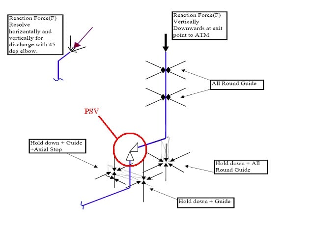
I place the thrust force at the outlet of the outlet pipe.
See "Where to Apply the PSV Reaction Force"

untitled1_adrmsu.jpg


If the outlet of the outlet is far away, not on a blow stack immediately on the valve, as in going into a flare line going to a flare stack, then put it at the end of the first elbow off the psv.

Valves that are attached close to the header may not be critical, since moment arms of the thrust force about the critical joints are short and perhaps the psv flow is not being vented immediately, but continue into a long flare line, hence you have sufficient restraint provided by the attachments to pipe in all directions.

The photo above is an immediate blow off in a high stack to atmosphere, the valve itself also on a high stalk of pipe. All moment arms are long and pipe supports are of miniminal strength, definitely undersigned, probably because the thrust force, if calculated at all, was placed close to the valve in the vertical direction alone, rather than at the top of the stack and maybe the horizontal component of that force from the 45° angle cut on the outlet was not considered.

--Einstein gave the same test to students every year. When asked why he would do something like that, "Because the answers had changed."
 
Design of a Flare system is complex. With so many PSVs, de-pressuring valves relieving to the flare header at different times and different set pressures, the back-pressure at the flare header is of importance when it comes to estimating the reaction force on a PSV.
For all purpose, we can say there is variable back-pressure that exists in the flare header/sub-header. With this in mind, in a closed system, the connected flare header will also provide some stiffness/resistance to the apposing reaction force. This is one of the reasons why headers and sub-headers should be always checked for Reaction Forces and vibration risk (even it is smaller in magnitude than open discharge),specially in de-pressuring system and adequate supports should be provided adequately.
In absence of any published Standard that allows to calculate these reaction forces in a closed flare system, without analyzing the flare system hydraulics, the best bet would be to use good engineering judgement and provide adequate supports in the Header/sub-header near the connecting point of the relief line and the header.

GDD
Canada
 
Status
Not open for further replies.

Part and Inventory Search

Sponsor