Continue to Site

Eng-Tips is the largest engineering community on the Internet

Intelligent Work Forums for Engineering Professionals

  • Congratulations KootK on being selected by the Eng-Tips community for having the most helpful posts in the forums last week. Way to Go!

Pull Away Load on L Bracket Top Leg - Hand Calculation 2

Status
Not open for further replies.

stressebookllc

Aerospace
Sep 25, 2014
163
Dear Friends, I have a bracket, a simple L bracket, with a couple of fasteners holding it down at the bottom base leg, and a horizontal pull away load at the top leg.

I am trying to figure out the reactions with hand calculations.
Two other scenarios are fairly straight forward statically determinate problems where the load is either pulling the top leg up or pushing it towards the fasteners and so are the hand calcs.
I have a couple of videos explaining them if you want to check them out:
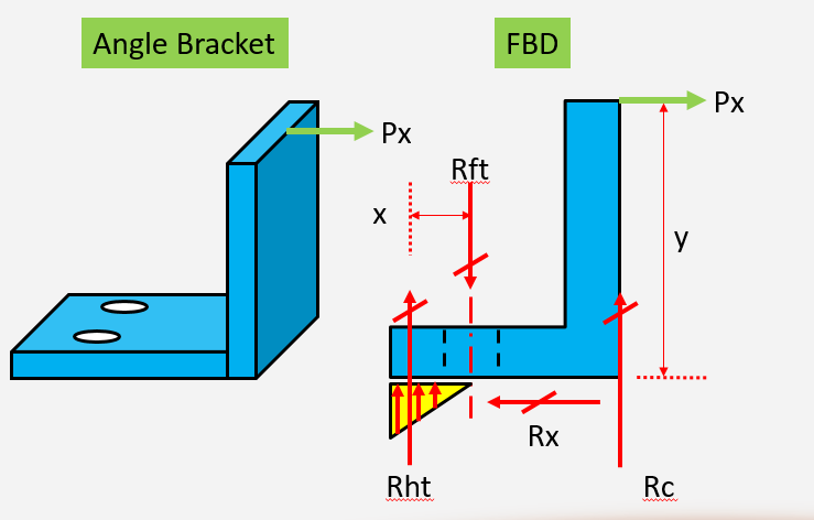
But the Pull away load scenario is a statically indeterminate problem with more unknowns than known equil. equations.

See figure below:
L_Bracket_Pull_Away_Load_lbnayp.png


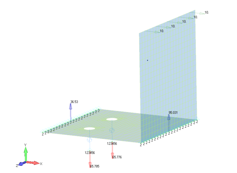
I built an FEM with the bottom L corner and the edge of the bottom leg constrained along Y (vertical) and the fasteners constrained along XYZ. You can see the running load of 10lb/in.

The reactions are as follows (don't worry about the long CBUSHs at the fasteners, and also I am only showing Y FBD loads, also assume the heel toe from the FBD above is not there, shift it to the edge)
Reactions_ma3jng.png


So is there any way we can calculate these using hand calculations? Its an approximately 5"x5"x5" angle and fasteners are at 3.4375" from corner. You don't ned to use exact dimensions.
Which law of compatibility can be used here to get that third equation I need to solve for all three reactions?

Also list your equilibrium equations please.

Thanks.

Aerospace Stress Analysis and FEA Courses
Stressing Stresslessly!
 
Replies continue below

Recommended for you

Unless I have missed something the problem is banal at an engineering level. Pretension in the bolts will not affect the forces due to Px, so you just take moments about the fulcrum to get the additional tension in the bolts Rft reacted by a vertical force at the fulcrum Rc, and a shear load on the base of the leg, your Rx equal to Px.

Cheers

Greg Locock


New here? Try reading these, they might help FAQ731-376
 
Prying force is a local phenomena. You can't represent it in your FBD. Whatever Greg said.

Spaceship!!
Aerospace Engineer, M.Sc. / Aircraft Stress Engineer
 
Thanks Greg, Rx is not a problem. It may look banal but is good for demonstrating FBDs and hand calculations. Shear and tension clips are some of the most common parts used in planes.

I guess I don't know yet how to solve this and verify the FEM results.

Aerospace Stress Analysis and FEA Courses
Stressing Stresslessly!
 
I just looked briefly, but you should be able to use the method of sections through the middle of the bolt section. If you separate the left and right half there you will find the internal moment on the right half to be Pxy. Using the definition of equilibrium to transfer that to the left side in the opposite direction and applying it to your FBD you should find that Rht*x = Px*y.

I should add that the function defining Rht and it's distribution, may not be correct as assuming a triangular distribution, it really depends entirely on the two materials in contact.
 
Could you show a picture of the actual physical boundary conditions. You don't usually have both the Rc reaction and Rht (as a triangular distribution heel-toe) as the same time.

Assuming there is just a support on the bottom of the picture (typical), then you have the Rc reaction if Px is positive (but not Rht). If Px were negative, you would the get triangular distribution, Rht (but not Rc). To get both at the same time would require some sort of supported base at the bottom and another support on top (sort of a clamshell or other scenario). Personally, I have not seen a configuration like that for brackets. Maybe that should be clarified first.

Brian
 
I have verified the deformation behavior with both scenarios (there is not much to mess up in this model):

1) Rc was NOT constrained vertically (in this case the corner moves down from the undeformed shape), the bottom left edge was constrained vertically producing Rht reaction couple with the fastener Rft
2) Rht NOT constrained vertically (in which case it also moves down from the undeformed shape) as Rc produces the reaction couple with the fastener Rft

The support is a flat surface under the bracket, typical to an L bracket used at panel joints.
Physically the overall behavior makes good sense to me as you bend the vertical leg away, but I am only looking for a way to do this assuming theoretical possibility.

In both cases the corner is being subject to a bending moment, therefore with the corner supported, the base lifts off at the corner right after the 90 degree turn from vertical leg to the bottom leg, Rc corner support turns into an edge support. As the bottom leg lifts off, the fastener is keeping it from doing so which results in the edge moving down but it is supported hence results in Rht

At the end we can see clearly in the FEM that Rft = Rht + Rc

gravityandinertia:
The scenario you described is fine for Px applied the other direction. In this case Rht will be equal to Rft.
Let us assume end support for Rht (the support will only shift it to the right due to heel toe)
In this scenario:
y is about 5.0"
x is about 1.5"
Px = 50lb

This means Rht = 50lb*5.0"/1.5" ~ 167lb = Rft

But the case in question is Px applied to the right as shown.
What I am seeing is about 37lb at the edge as Rht, about 95lb at the corner.

I need some kind of a compatibility equation. I have seen the law of triangular proportions being used, but this is when the reactions are going the same direction.
In such a case we can use the Ratio of Reactions = Ratio of moment arms (or sides of the similar triangles) and get an extra equation.

At the corner, I know the applied moment is Px*y, same as Px going to the left.
But there is also Rc right under it at the corner.

Overall Moment Balance About Rft:
What is/are the moment balance equation/s for the case in question? That's the part I am trying to figure out.


Aerospace Stress Analysis and FEA Courses
Stressing Stresslessly!
 
Are you sure you are not making a mountain out of a mole hill? This seems pretty straightforward based on the support scenario and the typical approach is (used for decades):

- Px positive: Assume a couple between Rc and the fasteners.
- Px negative: Assume a couple between Rht (triangular distribution) and the fasteners.

Both of these solutions are easily solved for (no compatibility equations required). There is an assumption that fasteners are spaced at typical 3D-5D (or so). Clearly a single fastener in a wide bracket would not exhibit this response.

Brian
 
If only I had a nickel every time I heard "it has been done like this for years"...

I am not disagreeing with all the years f experience here.

Basically the conclusion is to ignore the heel toe (Px positve), and the fastener load would be lower than what the idealized FEM is showing.

And that is fine too, I just needed a direction that's all.

By the way its two fasteners in there.

Aerospace Stress Analysis and FEA Courses
Stressing Stresslessly!
 
I'd say the point is that if you wanted to do it properly you'd need to account for the bolt pretension and elasticity and the elastic properties of the foundation. The resulting FBD would be rather different.

Cheers

Greg Locock


New here? Try reading these, they might help FAQ731-376
 
Both the FBD and FEM are wrong. In the FBD the triangular pressure goes on the right of the fastener, not the left (triangular pressure goes on the left of the fastener if the applied load is vertical or to the left). The line load reactions in the FEM are no where close to the actual reaction. To do the FEM accurately you will need gap elements between the angle and "ground". If you want to account for bolt preload the FEM becomes much more complicated.

ALWAYS plot up deformed geometry from a FEM (and not a displacement contour plot) to see of the loading, constraints, etc are reasonable.

But you DO NOT need a FEM to analyze this; just make some conservative assumptions about the reactions and be done with it. Thousands of aircraft were designed and certified without beating every stinking little fitting to death with a complicated FEM (that is a lousy approximation of reality anyway).

 
I thank you all for your generosity in responding and taking the time, I am really thankful.

I agree Greg, preload does make a difference. But the effective stiffness (Huth formulation) is usually employed for fastener shear flexibility of a joint.
For tension any load should be fine, if preload is ignored then any applied load upto the preload is tension in the fastener anyway, and beyond that is additive.
The difference with preload would be for the members being held together.

I respectfully disagree SWComposites.
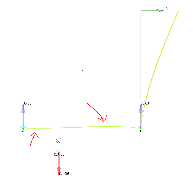
1) The heel toe is on the left, the right part lifts up due to the moment applied at the corner, this is what creates the heel toe on the left of the fastener.
2) What you are seeing is not a contour plot, its an undeformed plot of the reaction loads only, and if this FEM is seemingly overkill, which I feel at least caused some interest in this group of responses, then gapping is even more of that. The deformation behavior is straight forward and hence the constraints the way they are.
3) The line reactions are total reactions, they add up to the total fastener reactions, not sure what you meant by "no where close"
4) I have looked at the deformed plot (scaled up) and for the type of constraints and loading included in the FEM, the heel toe is on the left, I can post a picture when I get home
5) I know this type of bracket is not supposed to be FEM'ed, that is the whole point of this whole exercise is to do it by hand calculations, the FEM just gave me some additional insight into the behavior.

I guess the more realistic way to model this is probably to deform the top leg as a guided cantilever. This could be a typical joint, and could reduce the heel toe reaction.

It not about making a mountain of a mole hill, I genuinely am curious, this is what we do as engineers don't we? I appreciate you all beating down on me and I respect all opinions, but I do not believe my perspective is completely wrong on how this thing is behaving in terms of heel toe.

Aerospace Stress Analysis and FEA Courses
Stressing Stresslessly!
 
I really like the way SWComposites put it. "beating every stinking little fitting to death with a complicated FEM" :) (laugh)

The other thing he said gave me a headache though. Yes, he is very right: (turns out we oversized A350 wingboxes SWComposites, oh well, you will be safer than you would have been now)
The prying load phenomena is only applicable when the load is "vertical and in the upward direction only" (in other words: pulling load). This is due to the continuum of the material around the bolt, the material will try to go in the upper direction. The bolt will pull it from below - resisting the upward deformation. And then (this part is the killer) the rest of the material on the left side of the bolt will deform less "due to the bolt that was pulling it downwards". Thus, your whole material strain's continuity at all locations (remember elasticity courses in college) will "force" the material on the left of the bolt to apply pressure on area at the left of the bolt. This pressure will only be applied because of the material being pulled in the upward direction and the rest of the material will be trying to follow the deformation the rest of the material has around the bolt region.

You can't have this behavior with your 10N load to the right. That's a whole different thing. And in your plot, showing those reactions on the left side of the bolt as 36.53N(?) is also because of the FEA model you created.

I would sincerely advise you to run a SOL106 or SOL400 with contacts, friction coefficients. It is not hard. But it will show you the real mechanism behind your detailed FEM curiosity. If you get everything right, (you can get everything right in a day - nonlinear is easier than it seems) you may have a problem with EPSU and EPSW values (assuming you will use UW option in your NLPARM card). If you run into nonconvergence issues after you make sure you modeled it right, try playing with these parameters for EPSU and EPSW. They are by default 0.0001 I think, get them up to 0.1 if necessary. You are not to sensitive with this simple model, you are allowed to play with those values as you wish really.

Waited for someone to respond to this post, finally felt the pressure to right this wrong. Hope it helps with some insight. I know we are not very non-linear in aerospace domain, and I did non-linear just because I had a job to do it for sometime and some research back in aerospace industry before. But, feel confident to go the extra mile to do research in nonlinear domain. It will tell you about all plasticity corrections or load redistributions we use in aerospace.

Though, space is cool. Just had an interview with SpaceX very recently, that was one of my top interviews ever. If you really want to go the extra mile, switch to space in the next years after learning transient/vibrational fatigue and non-linear/implicit analysis. Not sure about the explicit. You sound like a linear guy, so this previous sentence could be my best advice to you..

Spaceship!!
Aerospace Engineer, M.Sc. / Aircraft Stress Engineer
 
I guess you got the point:

Just trying to make sure you understood it good enough that you won't try to create a prying load in a freebody like this again.
There will be exceptions to this though. If you are analyzing like 5000-10000 loadcases, you have no way of checking this. So, apply the prying load assumption in "every" tensile CBUSH load on that fastener. This should complete my previous explanation.

But again, in the interior, you are looking at 10-20 maybe 50 loadcases at times. So, you might as well "automate" a freebody load extraction algorithm in Femap/Patran just to check in which direction your "top" load is (which was lateral in your snapshot).

Spaceship!!
Aerospace Engineer, M.Sc. / Aircraft Stress Engineer
 
Status
Not open for further replies.

Part and Inventory Search

Sponsor