Continue to Site

Eng-Tips is the largest engineering community on the Internet

Intelligent Work Forums for Engineering Professionals

  • Congratulations KootK on being selected by the Eng-Tips community for having the most helpful posts in the forums last week. Way to Go!

Pulley bolted connection torque 1

Status
Not open for further replies.

Arrow22

Mechanical
Aug 17, 2017
3
Hello, I could use a little help with a calculation that I've been struggling with.

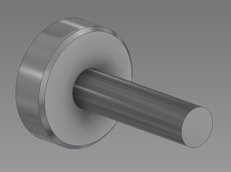
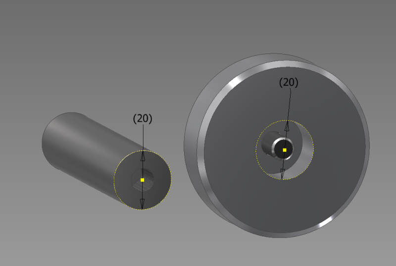
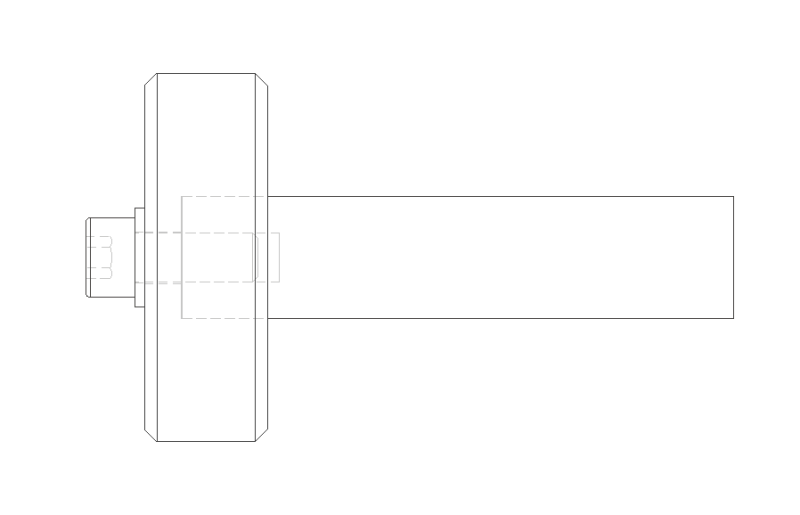
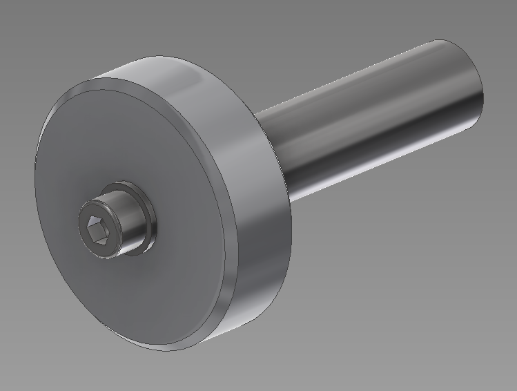
I wish to mount a pulley to the end of a 20mm shaft whereby a M8 cap screw will secure it, there won't be a keyway or any other method of preventing the pulley from slipping, only the friction from the contact of the end faces as this will be a slip fit onto the shaft.

So this is where I need a little help, I want to calculate the torque required to make the joint fail so the pulley slips on the shaft. The pulley won't actually be under massive load but I'd like to be certain it's not going to fail.

Here's a few pictures of it.

Cheers, Tom

Sorry for large images.
Pulley_zqlhvp.png

Pulley2_tz3lvj.png

Pulley_3_xoxqhg.png

Pulley_4_kucm0t.png
 
Replies continue below

Recommended for you

This is very simple, if you're not accounting for the belt load on the pulley.

You have a contact area and a bolt tension. Calculate contact pressure, which gets you the force limit between the faces.

If this is a real-world application, however, you may also need to account for the fact that the belt tension puts a bending load on that SHCS. This is not ideal because it can fail the SHCS but also because it has the effect of reducing contact area between the parts (as the 'top' of the pulley deflects away from the shaft and the contact area tips up on edge).

This condition makes it harder to keep the parts fixed, as the result is a net reduction in torque capacity.
 
Not meaning to offend, but IMHO this is a failure waiting to happen. I understand torque, friction, stress - all that stuff you can calculate. But in the real world this arrangement will eventually fail, for any one of a hundred reasons: reversing load, wear, deflections, creep, fatigue, you name it. Adding some anti-rotation feature is not that difficult, even if its just a set screw on a flat on the shaft (which I also do not recommend). The simplest way might be to just pin the pulley to the shaft with a roll pin. There are many options. Pick one.
 
Arrow22,

Go to Bolt Science and read up on bolt failures. Basically, bolts come loose when there is a mechanism that rotates them, such as the torque your pulley is trying to transmit.

--
JHG
 
Not that I'm advocating a pulley mounted to a shaft with a single bolt as the best approach.. it's not.

But to drawoh's point, whichever direction the pulley absorbs power in during service must be known, so that a left or right hand thread fastener can be properly chose.

You need to choose the threadform so that the service torque does not loosen the fastener.

If it absorbs or transmits power in both directions, you need to pick a more robust arrangement.
 
"The pulley won't actually be under massive load"

Is this an idler pulley, only subjected to radial load from a belt, or is the plan to transmit torque also?

If by chance the bottom of the bore or the end of the shaft are machined convex the diameter at which the friction is applied will be quite small, reducing the amount of torque resistance considerably.
 
 http://files.engineering.com/getfile.aspx?folder=cfd3da90-8363-4f3a-9791-f65537fea8cd&file=5_down_5_to_go_.gif
A taper fit between the pulley and the shaft would work much better.
 
A taper fit between the pulley and the shaft would work much better.

I second this. Works good on the crank damper of many engines.

There are a lot of ways to do pulley->shaft that will be reliable. The one you have shown there isn't one of them.
It would even be better to do a bolt circle of M3's if you absolutely must have a face-to-face connection.
 
A taper could work. If the pulley is just an idler, why fix it to the shaft at all? Put a bearing in there and let it rotate freely on a fixed shaft.
 
Much cheaper than a taper is Loctite. Works in blind ended holes as well. The proper old school way of doing it without machining tapers is a Fenner Taperlock hub or equivalent. If the thing is very light duty then keys or rollpins may work.


Cheers

Greg Locock


New here? Try reading these, they might help FAQ731-376
 
Thanks for your input guys.

I understand your concerns, the reason this came about is the shop has limited manufacturing capabilities and the steel shaft is case hardened to ~60 HRC. It's to be used in a non critical application and will transmit around 6Nm of torque in both directions. My calculations show the shaft will see a radial load of around 140N or 32lb.

I need a simple connection so I intended to use Loctite 648 retaining compound but having no experience with using the retaining compound I want to err on the side of caution a little, has anyone used this stuff before and do you think it'll be sufficient? I've heard it's the bees knees.
 
Ok... 6Nm is about 4 times what you can comfortably apply with a thumb and forefinger. That is, not a whole damn lot. Loctite 6 series is way overkill in that application,and is rather hard to undo.

Cheers

Greg Locock


New here? Try reading these, they might help FAQ731-376
 
"(taper) Works good on the crank damper of many engines."

I think a more typical damper connection on modern passenger car engines is a close slip fit damper, with a small key to align damper timing marks and timing sprockets properly, with a single relatively large bolt tightened HARD to clamp all the components against a shoulder on the crankshaft to handle belt driven accessories, and maybe most important, so no micromotions occur.

The successful recipe is Big fastener torque for high clamping force and resulting friction, and maximum interspecies contact diameter where the friction is applied so it can resist maximum torquage during operation.

Skimp on the installation torque, and the attachement shows what WILL be the result with a keyed application.
Without, a key the pulley will just slip and tear things up a bit.
 
Arrow22,

Loctite 648 is green stuff, right?

We used green Loctite (622?) to make sure dowel pins were retained. At some point, we decided the anodized aluminium had to be Alodined. The pins did not come out. We had to machine them out. Loctite shaft retaining compound is very effective. Follow the manufacturer's instructions. Since we were using aluminium and stainless steel, we applied primer.

--
JHG
 
Retaining compounds have massive amounts of data on bond strengths and temperatures.. but that's all based on close clearance or interference fit cylindrical surfaces.. I'm not sure I'd want to use it to bond flat parts together.

Maybe this is done all the time and I've just never seen it.
 
jgKRI said:
You have a contact area and a bolt tension. Calculate contact pressure, which gets you the force limit between the faces.

What?
 
If the parts are already hardened then the following would be tough do. I'd under-cut either the shaft or pulley so that the clamp load is reacted by an area away from the screw (so bigger radius to area and more torque capability). Also make your bolt "springy" by tapping the hole deeper and counter-drilling so you can use a longer bolt. Alternately you can use a thick spacer under the bolt head to get a longer screw.
 
MintJulep said:

Really?

Contact pressure, coefficient of friction, and mean radius are all that's required to calculate the torque limit of the interface. This isn't hard.
 
jgKRO said:
Contact pressureforce, coefficient of friction, and mean radius are all that's required to calculate the torque limit of the interface. This isn't hard.

No, not hard at all when you have [b]all the correct terms[/b].

 
Did you skip your afternoon coffee or something? It's Friday. None of us should be in a sour mood.
 
Status
Not open for further replies.

Part and Inventory Search

Sponsor