Continue to Site

Eng-Tips is the largest engineering community on the Internet

Intelligent Work Forums for Engineering Professionals

  • Congratulations IDS on being selected by the Eng-Tips community for having the most helpful posts in the forums last week. Way to Go!

Pump Automatic pressure control installation problem

Status
Not open for further replies.

ninjako4

Structural
Feb 17, 2016
7
Hello all,
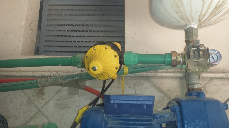
I have an inquiry regarding the Automatic pressure control DSK-8 (The yellow one(. (Check the pics below)
It does not work properly.
If I close the inlet valve, the device does not switch off the pump.
If I close the outlet valve, the device does not switch off the pump.
It was installed in a horizontal position instead of a vertical position.
Would you please tell me what could be wrong and how to fix it?

The device

20160611_085328_apqgrd.jpg


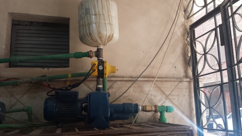
Installation
20160611_100900_za422p.jpg


Best Regards
 
Replies continue below

Recommended for you

You should sketch how you have connected the electrics .


It is a capital mistake to theorise before one has data. Insensibly one begins to twist facts to suit theories, instead of theories to suit facts. (Sherlock Holmes - A Scandal in Bohemia.)
 
Artisi, Thank you for your reply. I will sketch the electrics once I go home.
Do you mean that the problem is not that the device installed horizontally?
 
Does the instructions say anything about having to be installed vertically?

It is a capital mistake to theorise before one has data. Insensibly one begins to twist facts to suit theories, instead of theories to suit facts. (Sherlock Holmes - A Scandal in Bohemia.)
 
Read the installation instructions?

The unit only connects directly to small pumps. I suspect the green wires coming from the pressure guage have something to do with this problem.

Remember - More details = better answers
Also: If you get a response it's polite to respond to it.
 
Pressure gauge has nothing to do with the operation, all sensing in done internally. Normally start on drop of pressure run until no flow is taking place plus short run to pressurise the system. It has thermal overload protection and probably senses no water supply. They are usually very reliable, problem is possible incorrect wiring connection or a faulty unit.

It is a capital mistake to theorise before one has data. Insensibly one begins to twist facts to suit theories, instead of theories to suit facts. (Sherlock Holmes - A Scandal in Bohemia.)
 
Artisi,

Sorry, what I meant was the curious thing at the tee between pump and pressure bladder - looks like some sort of pressure switch with a guage on top - those look like some pretty thick wires coming from it ( but on looking very closely it might just be another hose??). The data from the unit says that it can only directly connect small pumps - hence needs to go via some sort of relay.

ninjako - how much time did you give the switch to do its job??? The white tank will provide flow and pressure for a while when the pump inlet is switched off and will also take flow from the pump whilst the pressure is low before the device will see a rise in pressure sufficient to turn the pump off.

Please also add what pressures everything is set at and what pressure and flow did you see during this "test".

Depending on volume, pressure and flow, this could take a few minutes or even up to 10 minutes before anything happens.

I really can't see orientation being an issue for a unit like this.

Remember - More details = better answers
Also: If you get a response it's polite to respond to it.
 
I just notice that you have the pressure tank mounted on the wrong side of the flow control unit, it should follow - not be prior.

Out of interest what is that horrible looking arrangement located directly on the pump discharge, get rid of it and rearrange the flow unit and pressure tank into their correct positions.

It is a capital mistake to theorise before one has data. Insensibly one begins to twist facts to suit theories, instead of theories to suit facts. (Sherlock Holmes - A Scandal in Bohemia.)
 
This is a pressure switch.it should not matter if it is before or after the pressure tank. It looks like the pressure adjustment screw is all the way in, so it is at it's highest setting, which is probably higher than the pump is capable of reaching. Turn the screw out while the pump is running until the pump turns off.
 
The OP wants the pump controlled by the automatic pressure control unit DSK 8, not what looks like the original pressure control switch, simply remove it and put the pressure tank after DSK 8.

It is a capital mistake to theorise before one has data. Insensibly one begins to twist facts to suit theories, instead of theories to suit facts. (Sherlock Holmes - A Scandal in Bohemia.)
 
Artisi, LittleInch, Compositepro, I would like to thank you for your informative replies.

Please excuse my terminology because I am not a mechanical or electrical engineer. (Please correct me if I use wrong terms).

LittleInch, the thick wires are another pipe line not related to my pump. (Sorry for bad angle).

Artisi, 1- The thing just above the pump is an old pressure switch (another type). 2-I agree that the pressure tank should be after the device because it keeps the water flowing inside the device and hence, keeps pump running for a longer time.

Compositepro, the start pressure for the device is 2.2 bars while the pump provided a higher pressure (7.5 bars).

Regarding the electrics:
The device came with the wires already connected to it. I made a "splice" to connect to the wires to the main line and the pump. I double checked that the wiring is done correctly.

Regarding the pluming:
I checked the device. There is a metal piece at the outlet valve that moves if I turn the device upside down. I blew air from the inlet (while the device was in a proper position like the 1st pic in the original post) and the piece of metal moved up and back again when I stopped.

So I thought this piece of metal is a part of the device's non-return valve which depends on gravity.

I rearranged everything like the below pic following everyone's advice and now the device is working correctly.

I have a last question, what is the max number of working hours for a pump per day?

20160613_064122_0_zikmwh.jpg
 
24 for a correctly sized motor,if you can get more good for you😊
Although I wouldn't think you will run continuously 24hrs / day--for applications like you are showing, the limiting factor is the number of starts the motor does per hour.

It is a capital mistake to theorise before one has data. Insensibly one begins to twist facts to suit theories, instead of theories to suit facts. (Sherlock Holmes - A Scandal in Bohemia.)
 
Status
Not open for further replies.

Part and Inventory Search

Sponsor