Eng-Tips is the largest engineering community on the Internet

Intelligent Work Forums for Engineering Professionals

Pump lost some flow after testing

MechNerd08

Mechanical
Sep 26, 2024
5
0
0
US
Hello All,

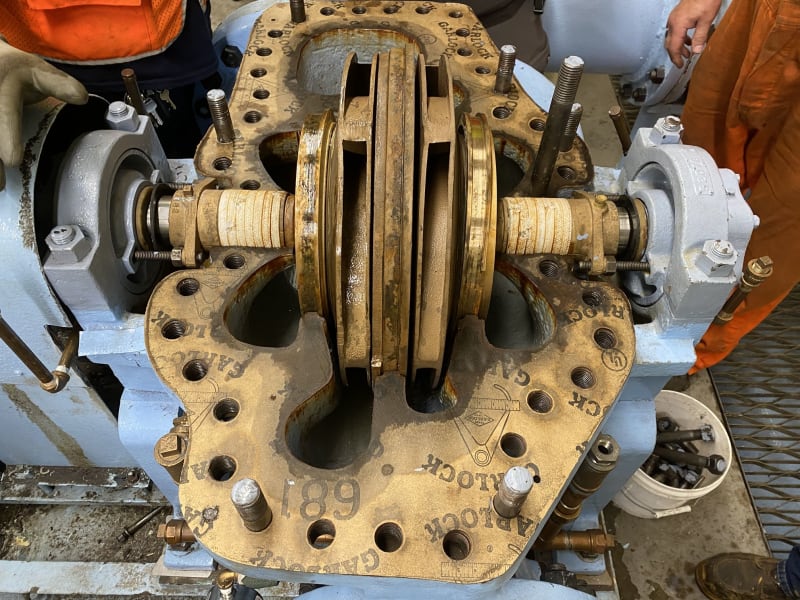
I did a pump performance test on a recently overhauled horizontal split-case pump for a potable water system. Under normal operating conditions, pump was operating slightly off curve (tank elevation was high) but was within our internal acceptable range. We typically do a pump performance test before returning pump for service to get a baseline for future troubleshooting and to verify how successful pump overhaul was.

However, I noticed that at pump shut-off, pressure was significantly lower than I expected and once valve was fully opened and operating under normal conditions, pump had lost about 360 gpm while the suction/discharge pressures were the same as before testing started. Additionally, the pump sounded like it was cavitating or recirculating on the pump inboard side. Pump was shut off and verified no air was trapped in the pump and all valves were ensured to be working properly or fully opened. Pump was turned back on and was still underperforming. Pump is across the line and speed was verified to be similar to before.

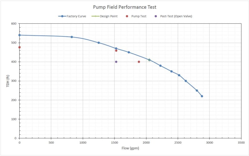
I am thinking that during shut-off, something internally may have shifted and is causing pump to recirculate inside the casing. Vibration slightly increased but assumed it was due to noise coming from internal. Could there be anything else that could have caused a drop in performance like this? Any help/advice would be greatly appreciated. Below is data from test and a graph of test points compared to pump curve.

Pump Design Point - 2050 gpm at 410 ft

Operating Point
Suction Pressure - 21.1 psi
Discharge Pressure - 194.4 psi
Flow - 1885 gpm

Shut-Off
Suction Pressure - 21.1 psi
Discharge Pressure - 229.3 psi
Flow - 0 gpm

Post-Test
Suction Pressure - 21.1 psi
Discharge Pressure - 194.4 psi
Flow - 1526 gpm

Capture_axqn4l.jpg
 
Replies continue below

Recommended for you

There could be some debris, but you'll only know if you strip the pump down.

The pump test at 1500 gpm looks suspect and not showing the same difference from planned head curve.

Check pump impeller diameter when you break the pump down for inspection.

Remember - More details = better answers
Also: If you get a response it's polite to respond to it.
 
Double check all instrumentation and readings before worrying about the pump.

It is a capital mistake to theorise before one has data. Insensibly one begins to twist facts to suit theories, instead of theories to suit facts. (Sherlock Holmes - A Scandal in Bohemia.)
 
Hi,
Make sure your instruments are calibrated with certificates before conclusions.
Is factory curve means from test performed at Factory, with report? Or pump curve from catalog?
Your shut off point @ No flow is very weird.
A sketch with the location of the sensors is welcome.
Good to download, read the materials:
My 2 cents.
Pierre
 
Thank you all for the responses. Provided a little more info.

LittleInch - Sorry, I should have clarified the points a little better. Points labeled "Pump Test" on the graph are data points taken during pump performance testing and the data point at 1500 gpm is with a partially closed valve. We plan on removing pump case sometime next week to inspect rotating assembly and verify there is nothing blocking the suction.

Artisi - Made sure all reading were correct. Initially suspected flow meter as there is typically a delay when flow is "catching back up". Waited a few minutes and flow did not fully recover so I started suspecting an issue with the pump. Additionally, there are 3 adjacent units which were on before and after the test and the adjacent pumps were within design flow verifying flow meter was working properly.

Pierreick - Used digital pressure gauges on taps located on pump. Gauges were checked against station pressure gauges when valve was fully open and taking head losses into consideration, were displaying similar values. Station pressure gauges read pressure on the suction/discharge headers. Flow meter is down the line on a common header for the station and pump in question was the only unit running when testing was being done. Thank you very much for providing those references.
 
I've witnessed similar performance variations on end-suction centrifugal pumps where there is some rubbing between the case and impeller. Either from binding during installation, or getting the shim stack wrong when building the pump.

We'll see it during runoff testing, a duplex system (1+1 backup arrangement) will have one pump that sounds a little grumbly, and won't make pressure or track to the curve like it should. Check the obvious running backwards and impeller diameter possibilities. If it wasn't one of those we'll usually find the discrepancy when the pump is getting re-inserted into the case and it won't cleanly install, or upon inspection while the pump is removed from the case it will be noticed the manufacturer did not install the seal/impeller/shim stack correctly.

In those instances there's typically one spot that will sound significantly worse when checking sound/vibration. Like a specific spot in the pump case sounds as if it is cavitating internally.
 
Rputvin - Sounds very similar to what I am experiencing. Pump rotation was verified prior to testing and our repair shop did not trim the impeller during overhaul. When vibration was measured after performance testing, it increased slightly from baseline reads taken just before performance testing started. If there is rubbing inside the pump, it appears that it is minimal. Thank you very much for sharing your experience.
 
Always difficult to analyse installation problems from a distance, however the very basics should be checked initially before removing and dismantling pumps.
1, is rotationc correct
2.have gauges been checked
3. are all valves fully operational and open,
4. Double check everything, never assume it's ok, that includes information being relayed from a second or 3rd party.

Remember, pumps are dumb - they know nothing and only perform within the system they are installed. If I have a dollar for every pump reported as ", something wrong with the pump" when it was really a system / application problem, I'd be a wealthy person.

It is a capital mistake to theorise before one has data. Insensibly one begins to twist facts to suit theories, instead of theories to suit facts. (Sherlock Holmes - A Scandal in Bohemia.)
 
Hi,
BTW, did you check for power measurement during the test, this will help you to confirm the flow rate?
You did not reply about the report (performance) from vendor after repair.
Sure about suction line and strainer (all clear and clean)? No temporary strainer in place?
Same for rotation, match the arrow on the pump?
Can you share info about the brand and serial number?
Good luck.
Pierre
 
Thank you all for the responses.

georgeverghese - Yes, there is an air/vac valve on a port located on top of the case. Verified air/vac working properly and pump is fully flooded.

Artisi - Thank you for the advice.

pierreick - Yes we did, confirmed amp reads at 62 amps (FLA = 69 amps). We do repairs in-house and field test I did was to verify success of overhaul. No strainer located on suction side, however, I am starting to suspect a blockage may be culprit. Verified rotation. Brand is a Goulds S/N 230B657. Thank you!

bimr - Unfortunately our repair shop does not have testing capabilities. Our only chance to test is after pump has been installed.
 
Hi,
I believe you have spare pump in your workshop, consider making a change and send the pump to the manufacturer or service repair company to get it fixed and tested with a certificate. You will save time and money.
My 2 cents.
Pierre
 
There is a reason that pump repair shops have pump testing facilities. The pump test confirms that the repairs are done correctly. Consider sending your pump to a shop that has testing facilities. That will eliminate the uncertainties such as flow meter accuracy, discharge headloss, etc.
 
HiMechNerd08,
If I understand you correctly, a shut-off pump test was performed. Centrifugal impellers normally have a minimum flow limit due flow stability and a minimum flow limit due to thermal liquid properties. The stability limit has to do with the impeller not being alble to throw the liquid outwards (I skip here the exact reasons as they are complicated). The thermal limit has to do with the motor putting in more heat than leaves vía the pump discharge, netto heating up the liquid in the pump. This leads to a boiling liquid in the pump. One of these or both could be applicable to your case.
Success
 
Hello all, I wanted to give an update on this. Pump cover was removed and it was found that the second stage impeller wear ring shifted outward. This coincides with recirculation/cavitation sound we heard and explains the loss of head at shut-off and reduced flow when valve was returned to fully open position. Appears that set screws were not installed on impeller wear ring on second stage which caused wear ring shift during testing at shut-off head. Rotating assembly has been pulled and repairs are underway. Thank you all for the advice. Below are pictures of pump with cover removed.

IMG_1404_dlm8hr.jpg
IMG_1405_apuown.jpg
IMG_1407_gabjxi.jpg
 
Good luck with that, but I would be surprised if that's the cause.

It is a capital mistake to theorise before one has data. Insensibly one begins to twist facts to suit theories, instead of theories to suit facts. (Sherlock Holmes - A Scandal in Bohemia.)
 
Back
Top