Eng-Tips is the largest engineering community on the Internet

Intelligent Work Forums for Engineering Professionals

Pump / Motor internal leakage on Hyd system

Status
Not open for further replies.

barbican

Electrical
Jul 15, 2012
20
0
0
IQ
Hi

I got a Hydraulic Winch which runs out of two pumps which are paralleled, the winch is rotated by 4 A6VM motors, the whole system is a closed loop system. i got currently a problem where i am losing charge pressure from the compensation pump during winch operation, i suspect one of the motors are leaking inside and causing this issue because we had all pumps replaced not long ago on the system. My problem is that i'm unable to find any data for the flow rate on the Case Drain on these motors (A6VM), any ideas from some one who have experience with these motors on what the case drain flow should look like ?.


Thanks

Marvin
 
Replies continue below

Recommended for you

The Two "RHZ 20 SR" valves get feed by the TAP60 Pump, if you follow the lines to these two check valves you will see that they are feed by the TAP60 pump.

you are correct, the brakes operates of the TAP60 pressure as well, but because of something that is dropping the pressure on the TAP60 pump, the brakes are losing pressure as well. once that happen i will stop the hoisting to prevent getting the brake packs welded.

The TAP60 pump has been replaced with a new one and has been tested.


The system was working prefect after the pump replacement. this problem happened just recently and just suddenly.

Swapping the control valves is a good idea to do a simple test, will definitely try that.
 
Why were all the pumps replaced?

Also - I'm tired of looking all over the drawing - what zone are those check valves?

Found them - those provide identical pressure to both sides of each pump and don't seem to be critical to pump function as much as to bleed air from the system.
 
Ideas:
Are the H62 valves properly closed?
Look for particles in the filters. If it is bronze it must be from abnormal pump or motor wear. If it is black or white plastic it may come from the 1/4 turn valve seats. In this case after a complete shutdown of the whole system and zero pressure everywhere, the lever of the defective valve turns freely.
 
Another idea: If the function trav. gear works well and that the hoist gear function does not work well: look for the fault in the part of the diagram which is used only for hoist gear. That is to say "EC" side of F60A
 
The H62 Valves are closed and even if they were open would not cause a problem of this sort because there is an flow restriction orifice in series with each valve.

these valves are used for emergency operation of the winch in scenarios where you need to release the brakes and lower a load. motors will start to turn due to the hanging load, the oil flow produced by the rotation of the motors will go trough these orifice's once the H62 valves are open, the orifice's are there to limit the speed of rotation of the motors during lowering.
 
If one of the A4VG pumps is totally unresponsive as you say then I would find that highly suspicious. Have you measured the case flow from it?

One of the steering pumps is also used as a feed pump. There is proportional relief valve in that circuit, it could be something with that.


To 3DDave: You should take a look at the concept of closed loop hydraulics. Here is a good start:
 
What I find odd is that the A6VM motors are driven by the A4VG 250 pumps. The RHZ 20 SR valve you mentioned is on the AV4G 180 circuit.
 
Hi Jacc.

That steering pump you are referring to dumps its oil to the main hydraulic tank once the relief valve opens at 290 Bar, it is not connected to the feed pressure system.

I am currently in progress of replacing the pump which is unresponsive with a new one, that is because i am out of ideas. i'll let you know of the results.


PS

its so damn difficult to do a case drain test on this system, all the pumps are connected to pipes instead of hydraulic hoses, the case drain pipes are branched to all the other motors and the space between everything..... you can barley fit your arm between these pipes. a such test will require me to modify a lot of the pluming, something i don't want to even think about, due to the amount of things that have to be considered.
 
Jacc - very informative, but doesn't address the problem. I am right fundamentally if oil is expelled to the tank then there would be voids which the charge pump is responsible for eliminating.
 
"That steering pump you are referring to dumps its oil to the main hydraulic tank once the relief valve opens at 290 Bar, it is not connected to the feed pressure system."

It seems to me the W port goes into the feedpressure manifold. Yes, no oil unless the valve opens but it is controlled by a proportional valve so potentially it could ad to the feed circuit. If it was a normal relief I would think it would be connected to tank.
 
Hi Jacc.

I have reviewed the Schematic and indeed that pump does serve as well as a feed pressure pump, but only for the Luffing cylinder and it's pump lines. it is controlled by the 4L-Y02 valve which is always closed during steering mode. I can't find any path for this circuit to get oil into the other main feed pressure circuit which is supplied by the TAP60 pump.
 
The hand pump is used as an emergency to open the brakes. There is a valve between the brakes and the low pressure side of the closed circuit to ensure the boost pressure during load descent. Have you done a test with the H62 valve closed to see if there is a lot of internal leakage in the closed circuit?
 
Hello,
The hydraulic diagram of the hoist gear is perfect for selling spare parts. But not for the image of the manufacturer to whom we will blame a very low lifespan. You must absolutely add a normally closed 2/2 directional valve plus ø7mm nozzle between the B of the A6VM motors and the A7 filter. A Hydac WS10Z type dispenser without a nozzle may also be suitable. And supply the distributor coil when the pressure at A of the A6VM is greater than 50bar for more than one second. Rexroth will never make the warranty with this scheme.
After each opening of the circuit, it is advisable to clean the circuit: Bypass an A6VM motor, supply the distributor coil, tilt a pump to 25% of the maximum flow and have hot oil.
 
Hi, unfortunately i have not been able to slove the problem yet, this has left me to uninstall and inspect every hydraulic component separately, so far i have inspected almost half of them.

I will for sure let you guys know what was causing this once i disocver the cause.
 
Hello Barbicane,
A lot of work to intervene on such a system!
A photo of the A6VM or the Rexroth reference should show if the exchange valve is installed when it is not shown in the diagram.
If there is no exchange valve: when you cycle at low load and high speed, the temperature in the closed circuit rises too high. In this case the viscosity becomes too low and there is abnormal wear at least of the distribution plates of the pumps and motors. You should notice that the gaskets on the pump and motor flanges are burnt.
For my crop: what type of oil is used on these cranes?
Good luck
 
Hi 73lafuite.

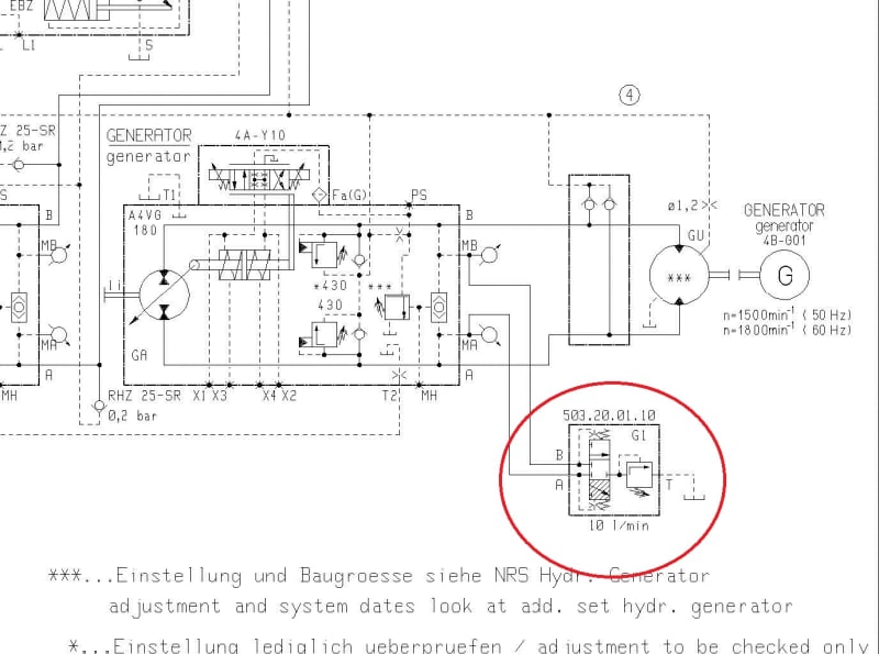
The A6VM's on the system does not have any exchange valves, the only exchange valve i have discovered in the system is the one mounted at the generator pump. on the diagram it is located at the lowest right and has the 503.20.01.10 as a part number. i checked that valve and it is working ok.

i have already taken apart all pumps by now for inspection and i am impressed by how clean they are considering a unit which runs for 3 to 4 days continuously every week. i'm no hydraulic design expert but what i can say is that these machines has been running on the same original hydraulic parts for over 10 years on this design. they do get hot but we never had a problem.

shell tellus 68 is the oil that is being used.
 
D_1_xsf7wx.jpg
 
Status
Not open for further replies.
Back
Top