Continue to Site

Eng-Tips is the largest engineering community on the Internet

Intelligent Work Forums for Engineering Professionals

  • Congratulations SDETERS on being selected by the Eng-Tips community for having the most helpful posts in the forums last week. Way to Go!

Pump piping Layout

KunAbdel

Mechanical
Mar 8, 2025
13
So i was reading about this topic and I found this


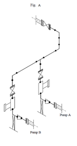
"Figure “A” below shows an ideal configuration of piping, in which the piping distance between each nozzle is minimized. In the case of hot oil piping, differences in expansion occur between the suction piping of pump A and that of pump B, according to the operating conditions of these pumps (pump A: operated, pump B: not operated). This poses problems with thermal stress analysis or causes dust and the like, which accumulates within the piping system, to center on Pump A strainer, which therefore is likely to plug. This configuration, therefore, is not employed for piping handling high-temperature fluids or fluids which are likely to cause plugging (tower bottom, sludge line, etc.)."

so the question is : what should be the arrangement when the fluid is a high temperature fluid??And why will the strainer be plugged in that case??
 

Attachments

  • xxxx.PNG
    xxxx.PNG
    20.2 KB · Views: 28
Replies continue below

Recommended for you

Your question makes no sense.

Hot oil and thermal expansion needs careful design, but the filter thing makes mo sense without knowing how these pumps are connected on tne inlet side.
 
Your question makes no sense.

Hot oil and thermal expansion needs careful design, but the filter thing makes mo sense without knowing how these pumps are connected on tne inlet side.
i shared a picture of the connection at the suction side. also do you want me to provide you with a link to the source ?
 
Maybe a side tap off the suction header to the lateral leading to pump A, instead of a bottom tap?

With pump sets in HT fluid service, where autostart of the standby pump is enabled, there is usually a warming line in operation on the discharge side of each pump that bypasses the discharge check valve. This is to prevent thermal shock on the pump that is autostarted. So this will keep the standby pump suction line warm. From a mechanical / piping design point of view though, it may not be possible to take credit for this warmup line.
 
I think that is a good arrangement for hot piping. The vertical down pipe will absorb thermal expansion difference between the hot and cold pumps more than if the common header was on the same elevation of the pumps and no vertical drops. The elbow supports would be free sliding. A piping stess analysis should be perform to check loads on pump nozzles.

You do need more straight pipe length between the elbows and the pump nozzles.

I don't think there is an issue with strainers in any case. Of course the one used more is going to get dirtier. Pumps are sometimes put on automatic changeover so that they wear evenly.
 
Last edited:
I think I see what the quotation of the Original Poster is trying to say. I assume this is a direct quote from the source that he found the layout diagram in. That the piping configuration shown is the most efficient as it is all basically fitting-to-fitting so it reduces the piping length and suction piping footprint. However it is not flexible since most of the components are rigid except for the tee and elbows, therefore it is inherently not flexible enough for hot piping. To make it more flexible just put some straight pipe piece in the vertical as necessary based on piping stress analysis. Also as mentioned above it does not include straight length before the pump nozzle.

Also in regards to the strainer, I believe what is trying to be said is that if you have a flow stream with heavy particles or sludge, it will fall down into the first vertical A strainer as it crosses over the tee and clog up the first strainer, even when the flow is to Pump B. This may be true if you have some very heavy things in the fluid and a low fluid velocity.
 
For high-temperature fluids, there should be a warm-up line, as @gerogeverghese has said.

fluids which are likely to cause plugging (tower bottom, sludge line, etc.)."
For these, provide duplex strainers with a facility for online changeover. DP across the strainers should be monitored, and change-over should be made on high DP.
 
Hi,
Check with those guys:
Looks not great.
Key on hot oil minimize the number of flanges to mitigate the risk of fire (leaks).

I don't buy the story about strainers at the pump suction for the reason above and other risks associated (burn). Very dangerous.

Pierre
 
Last edited:
Ah. Sorry I was a bit short earlier.

I thought this was the discharge piping.

It is quite stiff for a hot oil system and having inlet lines come off the bottom of a heater is a no no for this exact reason. You come off the side or top. Otherwise debris can fall into pump A suction and block it.

"Ideal layout.." hmmmm. That's a matter of opinion and I would say its actually not very good myself.
 
I also thought this is a pump discharge line.
For a suction line this layout appears to be not a good one. 90 degree bend(miter?) just before pump suction will result in flow disturbances and may result in cavitation.
Yes, the line is stiff for thermal stresses. Straight length should be increased for imparting more flexibility.
 

Part and Inventory Search

Sponsor