Continue to Site

Eng-Tips is the largest engineering community on the Internet

Intelligent Work Forums for Engineering Professionals

  • Congratulations waross on being selected by the Eng-Tips community for having the most helpful posts in the forums last week. Way to Go!

Pump Run Problems

Status
Not open for further replies.

ar9

Civil/Environmental
Feb 25, 2013
30
All,

We have a vertical pump with discharge after pump, with CenterLine(CL) at El. +8'. We then have a 6' straight pipe (23" ID) with a 6" ARV on top. After the 6' of straight pipe, the discharge pipe has two (2) 90D Long Radius bend (vertical CL change), which brings the pipe CL to El. +2. (see attached schematic)

How do the 2 bends going down right after the pump affect the TDH? Does this create a suction effect, negative TDH? When we run the pumps, the AMPS and HP climb until the pumps trip. Can this be caused by low head?

Any help is appreciated.

-ar9
 
 http://files.engineering.com/getfile.aspx?folder=19ddc3e1-9d99-4251-9a6d-72db07f22b9c&file=Schematic.pdf
Replies continue below

Recommended for you

The missing information here is what happens after your 30 " pipe?

If this fills a tank and the water level is higher than the pump discharge elevation, the two bends have no significant impact ( a small amount of extra friction loss, but only equivalent to a few feet of pipe)

If the water level is less than the pump discharge elevation then yes it will act as a syphon and essentially lower the head at the discharge point to virtually zero.

The same applies to if the discharge just flows away.

In both instances it is doubtful that the pump can cope with this and what you describe is a pump running beyond it's duty point and off the end of its curve to the right hand side, resulting in increased power demand and eventual tripping on high amps and possibly high vibration.

To avoid this and reduce flow rate and climb the head you need to add pressure drop, either by adding a valve or possibly an orifice plate or some other sort of flow restriction.

First though complete the hydraulic description and state where is the end water level or pressure this pump is pumping into

Remember - More details = better answers
Also: If you get a response it's polite to respond to it.
 
To fully understand your application, you should post a pump performance curve.

This appears to be runout of the pump. Your pump is pumping at too great of a capacity because there is low resistance (differential pressure) to flow.

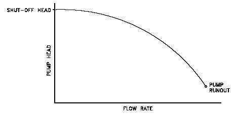
For a given centrifugal pump, the flow rate through the pump is dependent upon the differential pressure or head developed by the pump. The lower the pump head, the higher the flow rate. A specific pump has a curve of pump flow rate versus pump head called a pump performance curve. After a pump is installed in a system, it is usually tested to ensure that the flow rate and head of the pump are within the required pump curve specification. A typical centrifugal pump characteristic curve is shown below.

There are several terms associated with the pump performance curve that must be defined. Shutoff head is the maximum head that can be developed by a centrifugal pump operating at a set speed. Pump runout is the maximum flow that can be developed by a centrifugal pump without damaging the pump. Centrifugal pumps must be designed and operated to be protected from the conditions of pump runout or operating at shutoff head.

runout_xhqyyy.jpg


The pump may not have enough HP to pump at the rate that you are pumping.

Post the pump performance curve to confirm.
 
LittleInch - Thanks for the reply.

The discharge is open to atmospheric pressure. Therefore, we installed a weir so that it would create a tank operation . The weir brings the water to an elevation of +4 when the pumps are running (with this, the discharge pipe is fully submerged). You are right, the amps are climbing up and making the pump trip.

I thought about blocking the discharge end pipe in some sort in order to add even more pressure, but I wanted to confirm that the bends are not working against the system essentially. Would it be better to have a sort of pipe reducer right before the bends?

bimr - Thanks for the reply.

I do have the pump performance curve and it is not near the shut-off head, instead as LittleInch mentioned, it is going off the curve to the right side (getting into low efficiency)Pump Runout. We need to add head into our system and wanted to make sure that the two bends were not working against the system. We need more head in our system, do you think by adding an orifice block at the discharge end (after the bends) would drive us back to healthy pump operating points? It is currently running ~1' above the pump runout. (I will try to post the performance curve ASAP.)
 
The bends are not likely to have any significant affect.

The installation and use of an orifice plate or a valve to restrict the flow is recommended.

You can see from the following equation, that as the flow increases, the required HP increases as well.

How do I calculate Brake Horsepower Required for a centrifugal pump?

Brake Horsepower Required = GPM Required X (Total Dynamic Head) / 3940 / Efficiency

If you slow the flow down with a restriction, the HP consumed decreases.


Adding a suitably sized orifice plate anywhere in the system from pump discharge onward would help get the pump into a better place.

As said the elbows add a little bit more friction than straight pipe but the effect is very small.

Your alternatives are maybe reduce pump speed or alter the pump by taking out a stage or reducing the size of the impellor. All depends on cost and how many hours and days this runs for.

Would love to see the pump curve....

Remember - More details = better answers
Also: If you get a response it's polite to respond to it.
 
That's an interesting pump. I haven't seen many where power goes down at flow goes up. Given the high efficiency shown you really must be operating at virtually zero head. Try an orifice and see what happens.

Let us know what happens.

Remember - More details = better answers
Also: If you get a response it's polite to respond to it.
 
The orifice plate should have an orifice of 18 Inches diameter in the 24-Inch pipe. The orifice equation shows that would generate a headloss of 14 feet at 14,000 gallons per minute.

You might have to experiment a little with the orifice size.
 
I appreciate all your answers bimr and LittleInch. I will keep troubleshooting and post once resolved. I was thinking of an 18" opening for the orifice. I will let you know how that goes.
 
It is obvious that the pump is axial flow design, high flow, low head, very steep H,Q curve with increasing power with increasing head. Running at end of curve is normally no problem within NPSH constraints.
What is causing the overload - good question, is the motor correctly sized, is the impeller hitting the casing.
Can see no obvious reason for overload if the motor is correctly sized.

It is a capital mistake to theorise before one has data. Insensibly one begins to twist facts to suit theories, instead of theories to suit facts. (Sherlock Holmes - A Scandal in Bohemia.)
 
What are the impeller curves A-D, diameter or impeller tilt.
Is thus a new or existing installation?

It is a capital mistake to theorise before one has data. Insensibly one begins to twist facts to suit theories, instead of theories to suit facts. (Sherlock Holmes - A Scandal in Bohemia.)
 
Artisi - Thanks for the reply.

It is indeed an axial flow pump as you have described. The impeller A-D curves are the impeller tilt. At this point, an impeller between C & D was poured. This is a new installation and when tested, had the issue of the pumps tripping. My concern was having low TDH and running off the curve, therefore, lower efficiency, and was wondering if this was the cause for the AMP's climbing.
 
Is this pump a single stage vertical pump with the pumping element down below el 0ft? You say pump discharge nozzle centreline is at +8ft? If so, is there adequate submergence to prevent vortexing? Do we need a vortex breaker here?

Shaft support bearing issues?

 
georgeverghese- Thanks for the reply.

It is a single stage pump. Minimum submergence is 5' per manufacturer and that is covered. As well, a splitter plate was installed in the intake bell to avoid vortexing.
 
Could the intake cowl be blocked or the pump impeller be seized up with mud or silt ? is this in river water service or something similar?

Any way of inspecting this shaft support bearing? These are now mechanical issues and getting beyond my depth..
 
Time for stupidity check,is the motor speed / power correct, is the pump rotation correct, has impeller blade angle been confirmed?
Don't assume rotation is correct unless confirmed by yourself - secondhand confirmation is always
suspect.
Has flowrate been checked and any pressure readings been taken?


Agree with George, it could be a mechanical problem.


It is a capital mistake to theorise before one has data. Insensibly one begins to twist facts to suit theories, instead of theories to suit facts. (Sherlock Holmes - A Scandal in Bohemia.)
 
For simple one flow rate systems like this, orifice plates are simple, cheap and easy to instal between existing flanges.

Remember - More details = better answers
Also: If you get a response it's polite to respond to it.
 
Why are we discussing orifice plates, this is an axial flow impeller, as flow reduces so does required power input.
On this pump assuming half C-D vane tilt and a head across the pump of 4ft - flow of 12000 gpm and efficiency of 70% - power required is approx 17hp which hopefully is a lot less than the installed motor.
We need to be looking elsewhere for the problem.

NOTE: see my next posting correcting an error in this post.

It is a capital mistake to theorise before one has data. Insensibly one begins to twist facts to suit theories, instead of theories to suit facts. (Sherlock Holmes - A Scandal in Bohemia.)
 
Status
Not open for further replies.

Part and Inventory Search

Sponsor