Continue to Site

Eng-Tips is the largest engineering community on the Internet

Intelligent Work Forums for Engineering Professionals

  • Congratulations KootK on being selected by the Eng-Tips community for having the most helpful posts in the forums last week. Way to Go!

Pump Sizing - Analyzing Siphon/Vacuum Effects

Status
Not open for further replies.

wright44

Civil/Environmental
Jul 8, 2022
14
Hello,

I have come across a problem that has me running in circles. I have looked through previous posts discussing slack flow and siphon effects in various piping systems but I am struggling to apply it to evaluate my problem.

We are trying to determine a duty point to provide to vendor for a pump to feed 400 gpm from a source tank to a feed tank at a higher elevation. Both tanks are open to the atmosphere. Below I have attached a basic schematic of the profile and attached what I believe the hydraulic profile would look like. The cattle trough is connected to feed via float valve that keeps it from overflowing. The Source Tank is consistently at ~8 feet of water and Feed Tank at ~22 feet of water. At the high point (1,000 LF, 1450 ft amsl), there is a vent that is manually actuated to release air during start-up, then closed. The suction line in the Source Tank is 1 ft off bottom of tank (pump at 1,000 ft amsl). The inlet line for the Feed Tank is 1 ft off bottom of tank (1301 ft amsl).

So here is some conceptual problems I have.
- How would this system actually operate without installing a vacuum valve to intake air at the high point?
- Would the pump TDH be reduced by any siphon/vacuum effects from the flow downhill from the high point?
- For selecting a pump, do we actually need two points? One point for start-up (TDH = 1450' - 1007' + friction) and lower flowrates, and another point with lesser TDH at 400gpm to account for potential siphon effects?

General Schematic (n.t.s)
Screenshot_2024-07-19_122151_urfvea.png


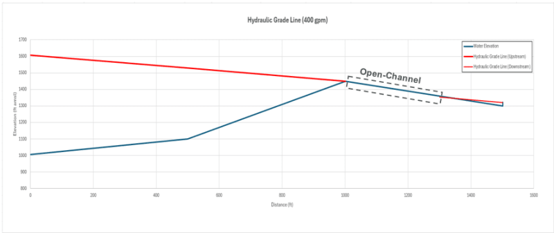
Hydraulic Profile
Screenshot_2024-07-19_122442_ytslkp.png


Siphon Effect (due to no air control?)
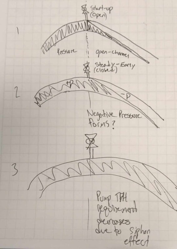
451639837_1219365809192767_8932457766457691789_n_sptezq.jpg


I believe the ideal solution would be a vacuum valve and eliminate any issues with air, but I want advice on how to analyze this system if it operated as drawn. I feel I am missing some fundamentals here.

Thanks.
 
Replies continue below

Recommended for you

I'm going to neglect the 8Ft of water in the source tank. Sooner or later that tank might be empty (due to maintenance, or a leak, both, or whatever). It's 3.4 psi on the helping side. You can take it into account later, if you like.

Let's look at your normal operating condition.
First of all, you need to clear the high point with a flow of 400gpm and get that flow rate going into the tank.

That takes 1450-1000 = 450 ft of head in elevation difference. You also need around 33 psi for the flow loss from pump to high point, which is 76 ft head. I used an ID of 4"to calculate flow loss in that 1000LF of pipe. So total head required to clear the high point is 450 + 76 = 526 ft of pump head, which equals 228 psig. A gage at pump discharge should read 228psig.

At the high point, you have 33psi in flow loss, making pressure there in the pipe equal to 228-33=195 psig - the water's new elevation of 450ft (195 psig) = 0 psig = 14.7 psia.

After flowing through another 500LF of pipe at 400 gpm with a 16psi flow loss, and a gain in head of 150 ft (65 psi) you wind up with 0psig -16 psig + 65 psig = 49psig as it enters your level control valve at the feed tank. 49 psig = 130 ft head. You could fill a tank to 130 ft. More than enough for your 22ft tank water level.

So at 400 gpm all the wat from pump to feed tank the pressure gage at the feed tank will read 49 psig

You're going to get a really fast flow at that valve. Likely much higher than 400gpm. If you open the valve just enough to get a flow out of 400 gpm, all the above pressures will stay constant. If you open up more flow, the pump will keep on flowing 400gpm to the high point holding 0 psig there, but the 500LF of pipe will start flowing much more at the outlet, being driven initially by the 49 psig pressure inside the pipe as you open the valve. The 500LF of pipe is emptying fast and the 49psig pressure in the pipe outlet is dropping quickly as the 500FL pipe empties, since the higher flow in the 500LF pipe is faster, you have a maximum of 49 psi differential pressure driving the flow, so it could be much more than what the the 16psi flow loss gave you atat 400gpm. A 600 gpm flow can develop with 49psi driving it through 500LF of pipe. You have 400gpm going in at the high point, but with much more outflow at the feed tank. If you don't slow down the outflow, you may reach slack flow conditions soon. That will happen when you reach 0.5 psia at the high point, the water's vapor pressure. Since there is 49 psig at the feed tank gage when there is 0 psig (14.7) psia at the high point, you know slack flow begins when your feed tank gage reaches around 49psig -(14.7psia-0.5 psia) psi, or about 35 psig, as you reach vapor pressure at the high point.

If your pump will not support the higher 600gpm flow rate at the 228psig, 526 ft head at max slack flow, then the 600gpm max slack flow rate will be temporary and you will eventually reach a 400gpm flow at slack flow conditions prevailing if you hold that 35 psig backpressure. Any lower pressure will give a temporarily higher flow rate at a lower discharge pressure.

(It's 2am here, so there may be a mistake or two in all that. I'll recheck in the morning).


--Einstein gave the same test to students every year. When asked why he would do something like that, "Because the answers had changed."
 
OK,

- How would this system actually operate without installing a vacuum valve to intake air at the high point?
It would simply operate in slack flow / open channel mode from the summit a couple hundred feet until the slope reduces. This is normally not a good thing, but realistically for a water line, it's not going to damage it.

- Would the pump TDH be reduced by any siphon/vacuum effects from the flow downhill from the high point?
Only down to 0 psig at the highest point for your TDH, but not really significant.

- For selecting a pump, do we actually need two points? One point for start-up (TDH = 1450' - 1007' + friction) and lower flowrates, and another point with lesser TDH at 400gpm to account for potential siphon effects?
No.

Personally I wouldn't bother with the air valve or vacuum valve.

If you added a back pressure valve atht tank set at about 100 ft head, you would avoid the vacuum condition when running but only add a few feet to your TDH to get the same flow. Up to you.


Remember - More details = better answers
Also: If you get a response it's polite to respond to it.
 
Checking

Let's see what pressure you need to get into the tank with 22ft head vs what you need to get over the high point to find out what is controlling the pump selection.

Finding out what minimum pump pressure is needed to pump the feed tank to 22 ft elevation above feed tank ground level.

Ground level = 1300msl
Tank water level = 1322msl
Min Pressure at feed tank inlet = (1322-1300)×62.4/144=9.5 psig

500LF flow loss at 400gom = 16psi, or 37ft head
Total head at entry to 500LF pipe = 1322+37= 1359ft msl

1000LF flow loss at 400gpm= 33psi, or 76 ft HD
Total head at beginning of 1000LF pipe = 1359+76=1435 ft msl.
Pump head = 1435msl-1000msl= 435ft
435ft = 189 psi

Pump head to clear the high point is 1450msl
+ 76ft head loss at 400gpm in the 1000LF pipe
=1526 ft msl
Pump head needed is 1526-1000msl= 526ft = 228 psig.

So the 526ft required to clear the high point is the critical case.
526ft head = a 228 psig pump discharge pressure.
That looks OK.

Discharge pressure at feed tank = 1526ft msl-1300 ft msl = 226 ft head
226 ft head minus flow losses of 33psi and 16 psi = 49psi or 113 ft
226-113= 113 ft head at feed tank = 113 x 62.4/144= 49 psig
That looks OK too.

--Einstein gave the same test to students every year. When asked why he would do something like that, "Because the answers had changed."
 
There are two important factors to consider. The first is whether the 500 LF section from the high point to the feed tank will run full and the second is to determine the pressure at the high point.

Using the Manning equation indicates that the 500 LF pipe would be very close to its full capacity if it were running as an open channel with only the slope as its driving force. So I believe that the type of analysis done by 1503-44 where the Darcy-Weisbach equation is assumed to apply is a valid assumption.

At the entrance to the feed tank the pressure must be 22 ft of water to overcome the static head in the tank. This is the starting point for the pressure analysis. To get the pressure at the high point we must subtract 450 ft for the additional elevation and add around 35 ft for frictional losses (assuming Darcy-Weisbach applies). This makes the pressure at the high point 22-450+35 = -393 ft. This is clearly impossible and what would happen in practice is that the water would vaporize and the pressure would be the equilibrium vapor pressure at the water temperature, or 0.25 psi at 60 F.

You should check if your piping can withstand this level of external pressure, but my recommendation would be to avoid the situation by installing a dual direction breather valve at the high point to maintain the pressure there at 0 psig.

With this type of valve in place the flow would be stable and the pump would see a steady head of 228 psig (526 ft) using 1503-44's figures. The flow in the pipe would have a Froude Number of 3.0 and this is more than enough to carry away any air that is entrained via the breather valve.

It might be tempting to take advantage of the vacuum that would develop at the high point and close the breather valve to lower the head the pump must provide and get some electricity saving. But the saving would be only 14 psi on a total of 228 psig and IMO not worth the risk.

Katmar Software - AioFlo Pipe Hydraulics

"An undefined problem has an infinite number of solutions"
 
If you put the vent at the high point, ensure that your SDR 11 is good for a full vacuum, because somebody will eventually close it and not tell you.

--Einstein gave the same test to students every year. When asked why he would do something like that, "Because the answers had changed."
 
SDR11 is good for full vacuum, but it won't stand that if you implose higher loadings by putting it under water.

Any valve like this on a pipeline is ripe for failure and maloperation. You don't need one so don't fit one. IMHO.


Remember - More details = better answers
Also: If you get a response it's polite to respond to it.
 
The answers here have been extremely helpful. I just have a few clarifying questions, working backwards in responses.

@LittleInch "SDR11 is good for full vacuum, but it won't stand that if you implose higher loadings by putting it under water."

How do I know whether a pipe is good for full vacuum? What calculations or sources can I use to check for this?

@katmar "This makes the pressure at the high point 22-450+35 = -393 ft. This is clearly impossible and what would happen in practice is that the water would vaporize and the pressure would be the equilibrium vapor pressure at the water temperature, or 0.25 psi at 60 F."

So essentially the maximum "advantage" you could get from this vacuum would be [ Absolute Pressure(@Temp, Elev.) - Vapor Pressure(@Temp) ]? But at the risk of collapsing your pipe?

@katmar "Using the Manning equation indicates that the 500 LF pipe would be very close to its full capacity if it were running as an open channel with only the slope as its driving force. So I believe that the type of analysis done by 1503-44 where the Darcy-Weisbach equation is assumed to apply is a valid assumption."]

So because the incline is so steep Manning's predicts that the pipe is running 99% full and would there experience Darcy-Weisbach losses? Therefore 1503-44's assumption that losses would apply is true.


I'll dig out Monday my little take from a vendor.

You need to have round pipe I.e. no ovaling or dent due to bending or other imposed load.

But I think SDR 11 is good for 50m water depth empty/ atmospheric pressure.

Your hydraulic grade line is spot on.

The issue you have is that when you stop pumping the pipe downstream the high point will drain and continue flowing for some time unless you turn the outlet off at the same time as turning the pump on on even close it first and allow the pump to pack the line then turn the pump off and isolate the pipeline.

Remember - More details = better answers
Also: If you get a response it's polite to respond to it.
 
I get about 118 feet friction loss in first 1000 feet of pipe using HDPE DR11 with ID = 3.63 inches. On the downstream side there is half of this value if pipe were flowing full, or 59 ft. Since there is 150 - 22 ft head = 128 ft available then the pipe should not flow full but velocity will accelerate until the velocity reaches a point where the friction loss equals the available head of 128 feet in channel flow as predicted by the manning equation.

Considering the elevation of the high point at 450 feet above pump then the differential pump head at 400 gpm:

450 + 118 - 7 = 561 feet.

Once it gets over the high point it will initially be at atmospheric downstream of the high point due to air initially in the pipe so when the initial fluid starts free falling into channel flow the maximum head required would be 561 feet.

Over time the air will be swept out or absorbed into the water then the vapor space will be at vapor pressure of the water. This would reduce the overall head but to be conservative I would not consider that a vacuum will form and just size pump based on atmospheric pressure existing on the downstream side of the high point. That would give you about 32 ft. of extra head.

 
Certainly use that method to select the pump head for whatever pipe you use. If you do not, ie you chose some other lower head, after losing the siphon for whatever reason, it will not be convenient to refill the siphon and restart flow. Its far easier to just restart using the pump at full flow rate, refilling the siphon and getting on with business as usual as quick as possible.

Yes, a pipe on that steep a slope at low flow rate will be flowing as a slug of water with vapor occupying the space above it.


--Einstein gave the same test to students every year. When asked why he would do something like that, "Because the answers had changed."
 
Thanks to Snickster for pointing out that the ID of 4" SDR11 pipe is 3.64". This makes the friction loss from the pump to the high point 50 psi (116 ft H2O) rather that the 33 psi we used previously. But even more important than this is the impact it has on the analysis of the section after the high point.

I was concerned that the Manning equation was indicating that the downleg section was running very close to its limit with a 4" ID pipe considered as open channel flow. But when using the ID of 3.64" it is definitely not possible for it to cope with 400 gpm when running part-full. Manning is usually used for slopes of between 0.1 and 10% and here we have 30% so the result of 320 gpm is questionable, but sufficiently below the target of 400 to indicate a real problem.

However, if we check the capacity assuming the pipe is full and use Darcy-Weisbach we get a capacity of 660 gpm for a slope of 30%. The required flowrate is between the Manning (320 gpm) and Darcy-Weisbach (660 gpm) values and it may be that we have a similar situation to trying to run a full pipe in the critical regime between Reynolds Numbers of 2000 and 4000 where the flow is not stable. I have no experience of running slack flow in this intermediate range and there may be vibration and surging - but it would be very difficult to predict the extent of this. It may run quite acceptably even with some surging but it would be good to get the opinion of someone who has done this before.

Without the benefit of real world experience of this flow regime I would like to see 6" used for the downleg. It would be possible to split this 500 LF section into 2, and use the 6" for the first 250 ft or so where it could work comfortably in part-full mode and then use 3" for the last 250 ft where the pipe would run full. The capacity of the 3" (2.84" ID) pipe according to Darcy-Weisbach is 340 gpm at 30% slope so the level would back up into the 6" section to provide additional head and ensure that the 3" runs full and provides 400 gpm. To get this split between the pipe sizes correct it would be necessary to get more detail on the actual fittings and valves used, and to look at the slope of the pipe if it is not a consistent 30% over the full length. A possible downside to the use of two different pipe sizes is that it would be less suitable for up-rating the flow in the future.

I am still convinced that it would be best to use a vent or breather valve at the high point to control the pressure there to 0 psig. I see that LittleInch has also assumed that the high point pressure would be 0 psig, but I do not understand what ensures that if there is no vent or breather valve.

Katmar Software - AioFlo Pipe Hydraulics

"An undefined problem has an infinite number of solutions"
 
The attached is what I've used in the past for hydrostatic forces / negative pressure on PE pipes. A bit basic, but it seems to work.

Basically on your main pipe, the issue which is getting my fellow posters all excited is because you are right on the limit of whether this pipe runs full or empty.

Run it at 350 gpm, it's going to be partly full d/s the high point.
Run it at even 425 gpm and it will be a full pipe d/s the high point. Definitely will be full at 450gpm.

The other thing is knowing EXACTLY what dimension a 4" PE pipe is. There are unfortunately many different standards for sizing PE pipe so if you can be precise this would help for OD and ID from the vendors catalogue.

At 400gpm based off your hydraulic line graph, if you introduce a back pressure valve set at 100ft of head (45 psi / 3 bar), this will ensure you line operates as a full line, but only add about 50ft to your pump head. It will still drain down a bit when you stop flowing, but that's ok.

IME vacuum / air valves work fine for 6 months then everyone forgets about them, the pits fill with dirt / leaves/ animals and in 5 years no one can remember why the pipeline is leaking and someone just isolates it and forgets about it.

Remember - More details = better answers
Also: If you get a response it's polite to respond to it.
 
 https://files.engineering.com/getfile.aspx?folder=77f0f50a-ec81-4d4d-b2c8-7910b5bb4299&file=PE_Buckling_1991.pdf
Thanks folks this has really been an incredibly informative post for how to approach these issues. I can see the arguments both for and against adding air valves, and also ways to evaluate the hydraulics in before scenarios. I feel more comfortable approaching this now.

@LittleInch Thanks for the advice and especially the guidance on PE buckling. I have saved it and I am sure I will be using it again in the future, as we primarily use HDPE.

@katmar I do feel some level of discomfort (and unfamiliarity) with the way Manning's works out in that downhill section. What I think i'll need to do to approach this further is evaluate under a more discrete profile. I don't know if just using the average slope is really enough information to evaluate. In reality I am sure it is far choppier. Folks at my firm also seem to be staunch air valve supporters, and not a big fan of utilizing vacuums in our designs. So that lends credence to avoiding the siphon situation.

@Snicksters Sizing it without considering the vacuum seems to make sense to me from a design standpoint for a problem like this. If we had a pump with a steeper curve it may not be all that sensitive and still produce close to the desired 400-gpm. On the other hand if this was a situation where the flow target was critical, a flatter pump curve might hurt when siphon does actually occur.

Thanks again folks.
 
No problem, glad we could help. Personally I've never really worked out why water pipe people like air vents so much. so long as you flow fast enough (about 1m/sec) you'll blow the air bubble out of any pipe.

I guess water supply systems often have very variable flow and no one likes gurgling water coming into their house, but a farm tank no one cares. But that seems to get lost in the "that's the way we do it" mode of thinking without actually engaging brain. IMHO.

Running any sort pipe in slack flow mode has issues which are best avoided as they make very little difference either to flow rate or head required at the u/s pump. You can't go below -1 barg at the highest point and probe more like -0.5 so the pressure drop from pump to high point reduces only very marginally.

Your system curve to overlay the pump curve starts at your high point (450ft) then increase due to friction losses. So your pump curve ideally crosses it at a decent angle so reduce the impact of small frictional losses on the flow rate.

Let us know what you finally come up with.

LI

Remember - More details = better answers
Also: If you get a response it's polite to respond to it.
 
Probably mirrors their preference for low pressure, intermittent flows, push fit joints, pipe dead ends, minimum power consumption and skinny pipe walls.

--Einstein gave the same test to students every year. When asked why he would do something like that, "Because the answers had changed."
 
In its right place then yes, you can see that it (vents) are needed. It's just when it isn't that I get annoyed. But then I've designed different pipeline systems all my working life.

Give me a water pipe system and I would make a complete mess of it....


Remember - More details = better answers
Also: If you get a response it's polite to respond to it.
 
I think you would do just fine. I've designed some oil field water flood collection and injection systems and salt dome storage brine handling pipelines just by changing the viscosity to 1. The flow rates and pipe Φ were far bigger than the oil production rates.

--Einstein gave the same test to students every year. When asked why he would do something like that, "Because the answers had changed."
 
I've done those, I meant a potable water distribution utility....

Same pipes, different world.

Remember - More details = better answers
Also: If you get a response it's polite to respond to it.
 
Status
Not open for further replies.

Part and Inventory Search

Sponsor