Hello,
I have come across a problem that has me running in circles. I have looked through previous posts discussing slack flow and siphon effects in various piping systems but I am struggling to apply it to evaluate my problem.
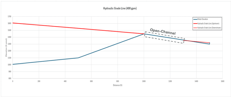
We are trying to determine a duty point to provide to vendor for a pump to feed 400 gpm from a source tank to a feed tank at a higher elevation. Both tanks are open to the atmosphere. Below I have attached a basic schematic of the profile and attached what I believe the hydraulic profile would look like. The cattle trough is connected to feed via float valve that keeps it from overflowing. The Source Tank is consistently at ~8 feet of water and Feed Tank at ~22 feet of water. At the high point (1,000 LF, 1450 ft amsl), there is a vent that is manually actuated to release air during start-up, then closed. The suction line in the Source Tank is 1 ft off bottom of tank (pump at 1,000 ft amsl). The inlet line for the Feed Tank is 1 ft off bottom of tank (1301 ft amsl).
So here is some conceptual problems I have.
- How would this system actually operate without installing a vacuum valve to intake air at the high point?
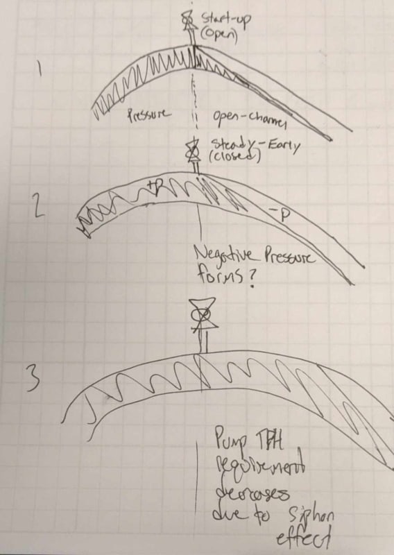
- Would the pump TDH be reduced by any siphon/vacuum effects from the flow downhill from the high point?
- For selecting a pump, do we actually need two points? One point for start-up (TDH = 1450' - 1007' + friction) and lower flowrates, and another point with lesser TDH at 400gpm to account for potential siphon effects?
General Schematic (n.t.s)

Hydraulic Profile

Siphon Effect (due to no air control?)

I believe the ideal solution would be a vacuum valve and eliminate any issues with air, but I want advice on how to analyze this system if it operated as drawn. I feel I am missing some fundamentals here.
Thanks.
I have come across a problem that has me running in circles. I have looked through previous posts discussing slack flow and siphon effects in various piping systems but I am struggling to apply it to evaluate my problem.
We are trying to determine a duty point to provide to vendor for a pump to feed 400 gpm from a source tank to a feed tank at a higher elevation. Both tanks are open to the atmosphere. Below I have attached a basic schematic of the profile and attached what I believe the hydraulic profile would look like. The cattle trough is connected to feed via float valve that keeps it from overflowing. The Source Tank is consistently at ~8 feet of water and Feed Tank at ~22 feet of water. At the high point (1,000 LF, 1450 ft amsl), there is a vent that is manually actuated to release air during start-up, then closed. The suction line in the Source Tank is 1 ft off bottom of tank (pump at 1,000 ft amsl). The inlet line for the Feed Tank is 1 ft off bottom of tank (1301 ft amsl).
So here is some conceptual problems I have.
- How would this system actually operate without installing a vacuum valve to intake air at the high point?
- Would the pump TDH be reduced by any siphon/vacuum effects from the flow downhill from the high point?
- For selecting a pump, do we actually need two points? One point for start-up (TDH = 1450' - 1007' + friction) and lower flowrates, and another point with lesser TDH at 400gpm to account for potential siphon effects?
General Schematic (n.t.s)

Hydraulic Profile

Siphon Effect (due to no air control?)

I believe the ideal solution would be a vacuum valve and eliminate any issues with air, but I want advice on how to analyze this system if it operated as drawn. I feel I am missing some fundamentals here.
Thanks.
