Continue to Site

Eng-Tips is the largest engineering community on the Internet

Intelligent Work Forums for Engineering Professionals

  • Congratulations KootK on being selected by the Eng-Tips community for having the most helpful posts in the forums last week. Way to Go!

Pump Upstream Higher Pressure Issue 1

Status
Not open for further replies.

nuuvox000

Mechanical
Sep 17, 2019
344
pumps_jienyh.png


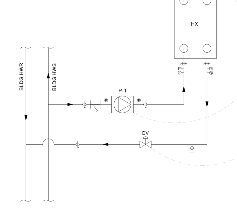
This is how I'd like to pipe in a new heat exchanger into the existing building system. The pump shown is variable speed. I'm concerned that the higher pressure HWS upstream water will push more water through the pump than required when the pump is running at low speed. Do you think this will be an issue? Curious if the pump will "resist" the additional turning of the impeller if the upstream pressure is trying to push water through, when it's running. Thanks in advance!
 
Replies continue below

Recommended for you

If water is pushed through a pump faster than a variable speed controller wants there is a risk of
Cavitation, if a centrifugal pump.
Energy being driven into the motor which needs to be dissipated in a breaking resistor.

Cavitation will be avoided if a positive displacement pump like a progressive cavity pump is used.
The energy problem is easily solved by using a 4 quadrant capable VFD, Including either a breaking resistor and /or a VFD capable of returning energy to the power distribution system.

The valve can be kept wide open unless the pump is unable to control the flow rate.

I realize this is a very non standard pump selection for an HVAC application, but I have used it in another application.
 
Just introduce a NRV bypass around the pump and monitor the pressures then turn the pump off.

But what does the valve CV control on? If flow is being controlled by that why are you bothering with a VFD? What did it control on?

Remember - More details = better answers
Also: If you get a response it's polite to respond to it.
 
It will be very hard to tune CV and VFD on series.

Each will react to changes caused by the other and you'll have induced oscillations.
 
Thanks for the great responses. I didn't think about cavitation, thanks for that. The CV control valve is just a simple open/close valve; opens when the pump runs and closes when the pump is off so that water doesn't flow through the heat exchanger when it's unwanted. The pump is controlled on a discharge air temperature from a fan coil on the other side of the heat exchanger.

I believe I did think of a solution to this; a pressure sustaining valve after the control valve and setting it to match the HWS pressure. That way it makes the downstream pressure and upstream pressure of the pump the same.
 
Depends how complex you want this to be and what the power of the pump is.

What exactly are the pressures here?

So how much flow can you get if you simply connect the HWS to the HWR via the HX? 25% of what you need? 50%?

How much more pressure do you need for the flow? If say the PD between S and R is 15 psi but you need 60 to get the flow through the HX then fair enough, but without some data here we're a bit stumped.

Why is the pump variable speed? does it go through some sort of controller measuring the difference between set point of the air and the actual air temp?

The back pressure valve idea would work but means more power used by the pump.

And most people would be confused by a Control Valve which just is an isolation or MOV on/off valve. Control valves usually control.

Remember - More details = better answers
Also: If you get a response it's polite to respond to it.
 
Provide the whole control sequence and control points. Can we assume the CV is digital (on/off)? What is the valve and pump control based on? Pressure, temperature????? What is the objective here?

What are pressures in the loop and what pressures needed for design HX flow? Will loop pressures be stable or fluctuate? Will required HX flow be variable or constant?
 
Thinking outside the box here....

What are the supply and return temps of your BLDG HW mains?

What is the rough flow in the Bldg HW mains?

What is the flow of your new pump?

What supply and return temps do you want on the other side of the heat exchanger?

 
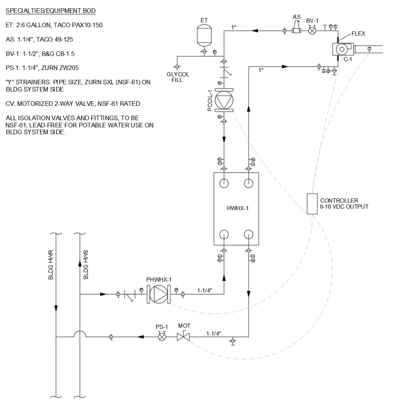
Sorry all, not ignoring you, just had to meet a deadline on another project. Here is the full diagram. This is a case of a PM telling me, "I already ordered the equipment and some of it is on site; can you just draw up a diagram to make sure I didn't miss anything?". Basically the pumps and heat exchanger are already on site so I'm trying to make things work, if possible. I'm currently trying to get some more information but just to answer some questions:

Pressures: trying to get that information but it's likely around 30 psi +/- 10 psi. I agree that it would be good to just connect it directly without a pump but then we would have to buy proportional control valves since we need to dial in the temperature. So I'm trying to make the pumps work if possible, which will be controlled with a 0-10 VDC input.

Why the pump is variable speed: see diagram, we're trying to maintain a 70 °F discharge air temperature from outdoor air that varies throughout the year between -10 and 100 °F.

Sorry for the control valve symbol confusion, wasn't quite sure how to show it.

"CV" (now "MOT") is on/off, yes. Loop pressures could fluctuate slightly, yes. But I believe the BLDG main pumps are set up to maintain constant pressure. HX flow to vary to maintain discharge air temperature.

S/R temps for bldg mains: 140/120. Flow will vary, there are 6 different locations across the building where this setup with occur. 9 pumps, each slightly different flow but all around 20-30 gpm. fan coil side of HX, looking for 138 supply and 108 return.
FULL_DIAGRAM_ss68pi.png
 
My conclusion so far is that FacEngrPE is correct about the cavitation issue. I see our options as injecting the return water back into the supply (robbing from it) or providing a pressure sustaining valve ($). Option 1 will require a full bldg review with the maintenance crew there and option 2 will require spending money. I think I'll offer this to the PM and let him choose. Let me know if y'all have better ideas; I appreciate the help!
 
OK, your building hot water supply and your fan coil hot water supply are too close for my thoughts. plus, I didn't realize you have multiple setups.

I was hoping your fan coil supply temp would be significantly lower. I was going to suggest pulling both your supply and return branches off the Bldg return, so that you would have no pressure differential created by the main building pumps. Obviously, that can't be done here.

You mention 30 psi +/-10. This is the pressure differential that you are expecting in the bldg mains? Measured where? That sounds high....not knowing any of the particulars. What else is on the building system aside from these heat exchangers?
 
That was a great idea though, something I didn't think of. Ok, looks like the supply pressure is 80 psi because it's a domestic/hydronic combined system on the building side. I just had a thought, I could probably use a PRV before the pump to take the pressure down and that would be a lot cheaper than a pressure sustaining valve.
 
Are you saying that your BLDG HWS and BLDG HWR lines are carrying water that is used for both building heat and domestic hot water?
 
Yes, that's correct. All the pumps, coils, valves, etc on the bldg side are potable water rated. It's pretty common in this one particular city we work in.
 
That would be illegal in most parts of the world and the added oxygen of potable water will eat your system. I hope no one is using that water for humans. Even in a shower you are inhaling water droplets.

If the pipe pressure is enough, you could use a modulating PICV. If it isn't, you use the on/off valve and modulating pump. but the pump is only needed if you lack the pressure.

Your control schematic lacks the temperature sensors. and is your on/off valve really controlled by 0-10V signal? that typically would be a digital output on the controller.
 
Yes, it definitely eats their system; they are using it for drinking, bathing, etc.

Unfortunately, the pressure is not quite high enough to do it with a modulating valve. The on/off valve is controlled by the pump; if it runs, the valve opens, if it stops, the valve closes. The variable speed pump is run off of a 0-10V signal from the discharge air temperature sensor.
 
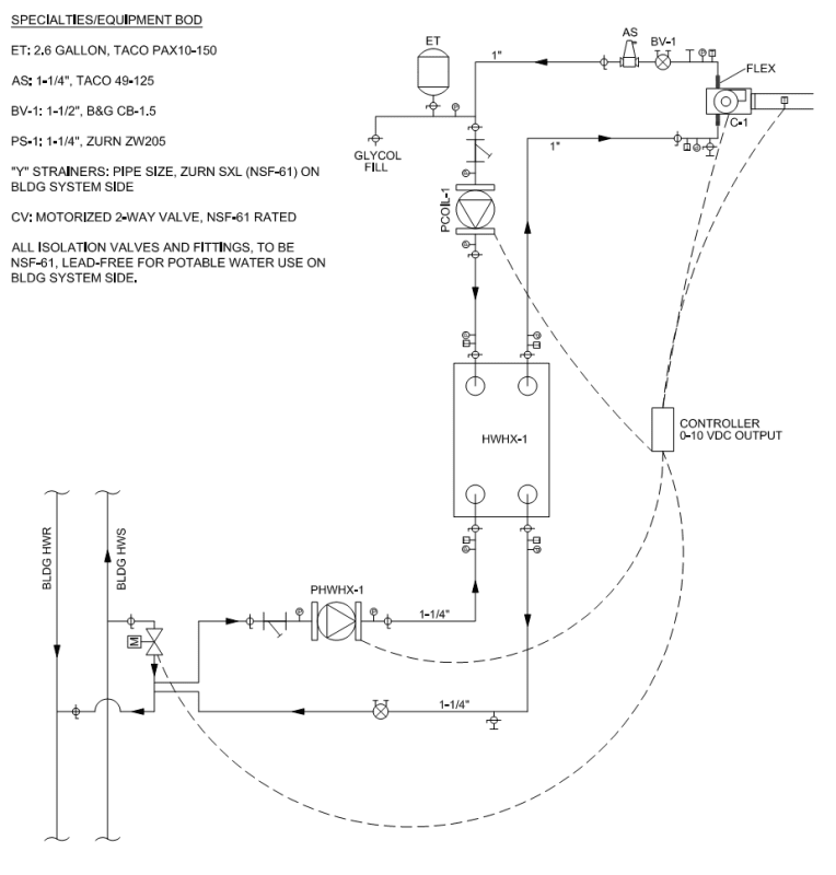
Is it the static pressure in the system or the differential pressure at the supply and return tap you are worried about? If you are worried about the differential pressure I would decouple heat exchanger pump from the building pump. The HEX pump will see the pressure differential caused by building pumps as water is moving between points A-B on attached. Do a cross-over bridge and put a primary - secondary connection for HEX pump. The pump will 'see' what ever static pressure in the building is present (as long the isolation valves are open)but it wont' see the differential pressure caused by building pump flow. I would put your two position control valve on the bridge, when you need to heat, this valve opens and the pump can injection any amount of water to the HEX as required, w/ the excess building water bypassing in the bridge. Keep the taps at C as close together as possible so the flow differential between them is negligible.

As far as the system you are speaking of that was somewhat popular in the late 90's. I think it was a called a tri-pipe system and it was actually a patented system. Can't say I'm a fan of them. EVERYTHING is potable water rated so selection of components is a pain. On cooling side they are actually tied to the domestic cold water and the fire-suppression system piping. I've only modified them, never designed one, and I don't like modifying them.
 
 https://files.engineering.com/getfile.aspx?folder=e1a88f8a-406b-4cfd-98ac-d89698377616&file=Decoupled_Pumps.pdf
I like that idea @MTES93. Cross over bridges with the control valve in the bridge. That eliminates the differential pressure concern caused by the main pumps.

Never heard of that combined domestic/heating system. Seems like it would be plagued with problems when there isa large domestic load. I assume that the domestic outlet pipes are connected to the HW Supply lines. That could leave very little flow in the return lines at times and erratic pressures it would seem??? I don't want any part of such a system.
 
MTES93, that's fantastic, thank you for that! Forgive my ignorance but what is that symbol you have on there with an "M" inside and two antennae? Here is my latest revision.
rev2_k2wux5.png
 
Agreed on that combined system. I don't know who thought all of that extra work and maintenance was going to be worth it, just to avoid running an extra pipe or two throughout the building.
 
Status
Not open for further replies.

Part and Inventory Search

Sponsor