Eng-Tips is the largest engineering community on the Internet

Intelligent Work Forums for Engineering Professionals

  • Congratulations waross on being selected by the Eng-Tips community for having the most helpful posts in the forums last week. Way to Go!

pumps of different head in parallel operation 1

Status
Not open for further replies.

terrorist

Mechanical
Aug 29, 2013
18
IN
hi all,
We have a set of three parallel centrifugal (between bearing) pumps for transfer of diesel. One of these three pumps has different head than rest two pumps for same flow rate. Although pumps run, most of the time, one at a time but sometimes two pumps are required to operate in parallel.
Now what are various possible problems low pressure pump may have to encounter with. Some of the things coming to my mind are...
1. For same percentage opening of discharge valve, higher head pump will deliver greater flow
2.Low head pump will deliver lesser flow than higher head pump and will push the operating point away from BEP resulting in decreased efficiency and increased vibrations.

Can we be able to draw equal flow from both the pumps?

Thanks in advance.
 
Replies continue below

Recommended for you

Depending on the pump curves and system curves the lower pressure pump might not flow at all, but is likely to have some flow as you describe.

Only by adding pressure drop on the outlet of the higher head pump can you get the pumps to be close to the same. This is best achieved with a control valve which can be adjusted, but an orifice plate might be able to do something. You do needsome sort of flow measurement on each pump.

Getting equal flow in parallel pumps is not easy, but all depends on your pump curves and system curves. If you get within 10% you're doing quite well.

Remember - More details = better answers
Also: If you get a response it's polite to respond to it.
 
Parallel pumping has been discussed on numerous occasions in this forum, is explained in most basic pump books and many links on the Internet. I suggest you do some research as a means to answering your concern.

It is a capital mistake to theorise before one has data. Insensibly one begins to twist facts to suit theories, instead of theories to suit facts. (Sherlock Holmes - A Scandal in Bohemia.)
 
Two (or three, or four etc.) flow circuits in parallel will each have the same differential pressure, or head differential. This problem lends itself to easy graphical solution.

Each pump circuit has its own pump curve, and a unique head loss for the local piping, valves, orifices within each individual pump circuit.

Construct a curve head vs flow, for each pump circuit, this will be the pump head, minus the head loss for the individual local piping circuit. Construct this curve for all flows, from zero flow to the maximum flow that could exist. Name this the "effective circuit net head-flow curve" for each pump circuit, say ECC1, ECC2, ECC3 . Note that a pump with a check valve in its circuit will have a ECC graph that rises to infinite head pressure at zero flow, not allowing reverse flow for any head pressure.

Draw all ECC curves on a single graph, then at all possible heads of interest, add the flows from each circuit. This is done for many individual head values, add the flow for ECC1 plus flow for ECC2, plus flow for ECC3, the resulting summed values give the total system flow (combined circuits in parallel) at each head of interest. The resulting curve is the effective head vs flow of the entire pump system, name this combined curve ECC123.

Now you have a tool that will tell the total flow to the system vs the head pressure capability of the multi pump system, curve ECC123. Knowing the total flow, working backwards at a fixed head value, you will know the flow in each individual pump circuit.

Graphical solutions such as this work well. Two simple rules: Parallel circuits share the same head, but not necessarily the same flow. Series circuits share the same flow, but not necessarily the same heads.

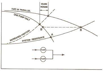
The graphical method allows finding an overall system flow by plotting the ECC123 as the active source, and the system resistance curve (pipeline & valve friction, plus static plus pressure differential requirements). The intersection of these two curves is the flow & head solution for the system.


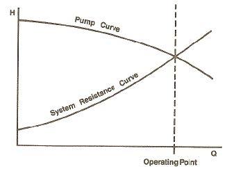
You should be able to obtain equal flow from the two identical pumps. However, to understand what will occur, you need to develop a system curve.

18-1_trpq6q.jpg


Overlay the pump performance curves on to the system curve to determine what to expect.

18-1ff_pdomom.jpg


Status
Not open for further replies.

Part and Inventory Search

Sponsor

Back
Top