Continue to Site

Eng-Tips is the largest engineering community on the Internet

Intelligent Work Forums for Engineering Professionals

  • Congratulations KootK on being selected by the Eng-Tips community for having the most helpful posts in the forums last week. Way to Go!

Punching Shear at Varying Slab Thickness

W460x68

Structural
Oct 22, 2024
5
Hi Everyone,

Long time lurker, first time poster. I have a scenario I would appreciate getting some opinions on. I am a Canadian structural engineer practicing primarily in the GTA (Greater Toronto Area). In return I promise to offer my opinions and advice on future threads where I think I can make valuable contributions.

I am checking punching shear in a slab at a column where the slab thickness varies within the shear perimeter. See image below. The 450 mm thick slab is a parking deck beyond the footprint of the building. The 1150 mm thick slab is a transfer slab that supports 8 storeys of cast-in-place concrete residential. The step occurs at the top of the slab - the underside of slab is flush (I have included a section). The factored punching shear load is 5260 kN. The unbalanced moments are negligible.

I have already checked assuming a 450 slab over the entire shear perimeter but, not surprisingly, was unable to get that to check out with or without shear reinforcement. My preferred punching shear reinforcement is stud rails. I'd like to take advantage of the increased shear capacity due to the presence of the 1150 slab within the shear perimeter, however I am unsure of how to quantify this in a reliable manner. Have any of you experienced a similar condition? How did you deal with it? Can I take a "weighted average" of the effective depth "d"? I appreciate any and all comments.

Additional info:
- 35 MPa concrete
- CSA A23.3-2014 concrete code
- d_(450slab) = 385 mm (effective depth)
- d_(1150slab) = 1095 mm (effective depth)

I am not looking to use any drop panels as the entire parking level is a flat plate. Moving/rotating the column may be possible but will be difficult due to layouts. I'd prefer if I can design for the current location. Reducing the load is not viable. Increasing the thickness of the 450 slab is not a great option as the rest of the parking deck slab works as a flat plate at 450 thick (deflection, flexural design, stud rails at some columns etc.).
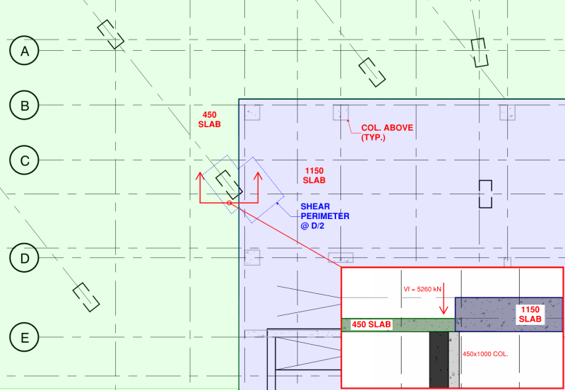
punching_shear_ambutz.png
 
Replies continue below

Recommended for you

There's a couple of issues I see with doing it your way:

1. There's a failure mechanism you're missing. It can fail at the interface between the 450mm and 1150mm slab, it's just not something we'd normally check because with a consistent thickness we know that this is a stronger failure point than the traditional shear perimeter. You would need to evaluate this as well. As a comparison, what would you be thinking if the column had 450mm of slab directly over it and then four inches out from the perimeter of the column the slab increased to 1150mm? There's clearly a mechanism in the 450mm slab even though the 'shear perimeter' would all be in the thicker slab.

2. You're not concentric to the load. This isn't a pure punch anymore. It has a twist to it This happens to a degree at free corners and things, but the load distribution is much clearer.

3. The 'unzipping'. This isn't ductile. What happens when the stress in the thinner slab exceeds the punching stress? It seems like it would need to crack there and then rotate to engage the thicker slab in the perimeter you've sketched. A partial punching failure would still be a problem, even if it didn't create a full collapse mechanism.

If you really wanted to do this, I think you need to try to justify load paths using strut and tie, or something similar, but the node rules are likely to punish you pretty hard and I can't see you getting your capacity that way.

I'd be more comfortable if you were primarily in the thicker slab and trying to get a little bonus capacity from the thin slab, but most of your bearing is in the thin slab, which feels pretty concerning and contrary to how you'd normally detail. There's some capacity there, it's just really worrying to mess with punching shear. It's a pretty cookbook requirement for a reason and playing around in novel ways when you can avoid it feels like a bad idea.

Have you thought about using a punching shear reinforcement scheme of some sort?
 
Yeah that looks really outside anything that's been tested or used to base the provisions on.
 
Assuming that the light dashed columns are consistently your columns being transferred - and the dark columns are your supporting columns - it appears that you have a number of critical flexural and shear sections that does not take advantage of the additional strength of the thicker slab. Negative moment/punching shear at column A.5/5.5 and A/7, positive moment at A.5/3.5....
 
Ew. If this is new build, I would seriously consider finding a way to just not do this.

How much of your punching shear comes in from the transfer slab vs the thinner one?
 
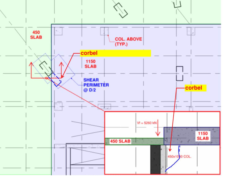
Nobody likes a field cast corbel but, if you can't move or enlarge the column, perhaps this is a viable option.

Based on the relative stiffness of things, I feel that it would be prudent to assume that all of the load delivered by the transfer slab comes into the column through that little, underlapped triangle at the right column. Maybe some load spread through the 450.

c01_kwn5cj.jpg
 
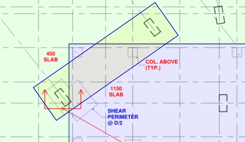
Or a shallow beam crossing under the corner of the thicker slab? This, also, will be unpopular and may cause head height issues.

c02_opofuy.jpg
 
It's surprising that the unbalanced moments are negligible when all the transfer columns are on one side. Because all the transfer columns are supported by the 1150 slab, i would have expected to see unbalanced moments and shear concentrated in the thicker slab because that's where the load is.

Because these situations aren't really covered in any books/standards to my knowledge and because all the transfer columns look to be supported by the 1150 slab, i would find it useful to also do a punching shear calc treating it as a slab edge. In other words, using the full thickness of the thicker slab and treating the thinner slab as if it were a void. I'm not saying to rely upon this calc for design, but it may be useful in getting a very rough idea of how hard the 1150 section of slab is working.

The only other things i could add is that i think you may be overestimating the shear perimeter in your sketch as i don't believe the re-entrant corner parts would exist, i would have drawn a straight line instead as this would give a lower capacity and therefore be critical. Also, you could always consider increasing the concrete strength of the pour, the price difference to the next grade up may not be that large if that works.
 
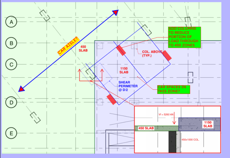
I'd be looking to rearrange columns / add additional ones to reduce the loads going into that 450 zone and make this situation a lot more favourable. Given a choice I'd rather avoid this situation entirely very early on in the coordination stages and have that 1150 zone extend fully over any supporting columns. This feels like the sort of failure that's even less forgiving than a normal punching scenario if you don't get it right

Guessing from the regular column arrangement, there's car aisle in the top left/spaces below the 1150 on the layout beneath? Usually there's a bit of play to add columns in that sort of situation as some of the car spaces already allow for those 1000x450s between. What's feasible is obviously subject to the actual layout / layouts on any additional levels below, but here's the sort of thinking I'd go for
MoarCols_hhjjbf.png


----------------------------------------------------------------------

Why yes, I do in fact have no idea what I'm talking about
 
Great points. You make a great case for trying to shifting the column completely below the 1150 slab. My plan is to use stud rails where shear reinforcement is needed.

EZBuilding said:
Assuming that the light dashed columns are consistently your columns being transferred - and the dark columns are your supporting columns - it appears that you have a number of critical flexural and shear sections that does not take advantage of the additional strength of the thicker slab. Negative moment/punching shear at column A.5/5.5 and A/7, positive moment at A.5/3.5....
Your assumption is correct and yes there another location where a similar scenario exists. The column location I'm highlighting in this thread has the largest punching shear.

KootK said:
Ew. If this is new build, I would seriously consider finding a way to just not do this.

How much of your punching shear comes in from the transfer slab vs the thinner one?
It's a new build. The responses from you and others have definitely convinced me to find a way to move this column under the 1150 slab to make things a lot easier to deal with. I don't have exact numbers but the vast majority of the punching shear comes from the transfer slab.

KootK said:
Or a shallow beam crossing under the corner of the thicker slab? This, also, will be unpopular and may cause head height issues.
Definitely an option although head height is at a premium in the below-grade parking level. I would have an easier time just moving/rotating this column below the 1150 slab. I see the punching shear being significantly easier to deal with as the 1150 slab will offer much higher capacity and I can quantify it much more reliably if the column is completely below and orthogonal to the 1150 slab edge. EDIT: layout won't permit rotating to orthogonal, but it can be moved completely under the 1150 slab.
 
cam_b said:
Because these situations aren't really covered in any books/standards to my knowledge and because all the transfer columns look to be supported by the 1150 slab, i would find it useful to also do a punching shear calc treating it as a slab edge. In other words, using the full thickness of the thicker slab and treating the thinner slab as if it were a void. I'm not saying to rely upon this calc for design, but it may be useful in getting a very rough idea of how hard the 1150 section of slab is working.
That is my plan for the transfer columns - a punching shear check assuming a "corner" or "edge" condition using the 1150 slab thickness and ignore the presence of the 450 slab.

cam_b said:
The only other things i could add is that i think you may be overestimating the shear perimeter in your sketch as i don't believe the re-entrant corner parts would exist, i would have drawn a straight line instead as this would give a lower capacity and therefore be critical. Also, you could always consider increasing the concrete strength of the pour, the price difference to the next grade up may not be that large if that works.
Unfortunately I don't think increasing the concrete strength will help enough that I would be confident in this working as currently sketched. Based on this thread and thinking through it more, I think I am better served moving the column and/or adding columns to alleviate some of the punching shear demand at this particular column, as suggested by Just Some Nerd.

Just Some Nerd said:
I'd be looking to rearrange columns / add additional ones to reduce the loads going into that 450 zone and make this situation a lot more favourable. Given a choice I'd rather avoid this situation entirely very early on in the coordination stages and have that 1150 zone extend fully over any supporting columns. This feels like the sort of failure that's even less forgiving than a normal punching scenario if you don't get it right

Guessing from the regular column arrangement, there's car aisle in the top left/spaces below the 1150 on the layout beneath? Usually there's a bit of play to add columns in that sort of situation as some of the car spaces already allow for those 1000x450s between. What's feasible is obviously subject to the actual layout / layouts on any additional levels below, but here's the sort of thinking I'd go for
You've got a keen mind - that is exactly the layout of the drive aisle and parking spaces. I like your approach of adding columns to reduce the load on the 450 zones and it may be possible to tweak the layout to accommodate that. I've got a call with the architect tomorrow to review this area with them.
 
Is there any way to adjust your transfer slab bounds as they relate to your current low column arrangement? When I think transfer slab I envision support columns fairly consistent around the transition from thick to thin. As noted above there must be pretty sizable moments that need to be resolved and the point of a thicker transfer slab is to add the section for shear and bending until it can be supported by a column below.

My vote is to either get the support columns completely in the transfer slab zone or provide beams that go from transfer slab to support columns.
 

Part and Inventory Search

Sponsor