Continue to Site

Eng-Tips is the largest engineering community on the Internet

Intelligent Work Forums for Engineering Professionals

  • Congratulations KootK on being selected by the Eng-Tips community for having the most helpful posts in the forums last week. Way to Go!

Punching shear checks for pile supported base slab with overlapping perimeters 1

Status
Not open for further replies.

chritsar

Structural
May 9, 2022
11
In the case of a base slab with a thickness of 60cm supported on piles with diameter of 44cm-60cm, we have a situation where the punching shear perimeters overlap (using EC2 parameters for Germany). The slab is loaded by walls scattered around. How could we check for punching shear of the piles that are close together in a straight line? The German NA specifically states that the zones must not overlap.

I have found similar posts but for pile caps that usually have more depth and/or have less flexural behavior and am not sure if it is safe to extrapolate to the situation above.
 
Replies continue below

Recommended for you

for overlapping zones you need to take a view to me. For instance you could add the shear stesses together as a conservative view. not sure about the german NA. for some foundations ive designed it would be impossible to not have overlapping zones for very heavy industrial buildings etc where you need more piles and/or a thick slab. for some that would render them undesignable. could you use the weight of the walls in the zone to reduce the punching load? (if there is no net tension above the pile there is no punching).
 

Can you post a descriptive sketch , excerpt of found. dwg ?
 
You can use some engineering judgment to create a punching shear perimeter around a "group" of pile or columns or such. Typically, when I have done this (using the American / ACI codes), I have still used the moment aspects of punching shear. It's actually relatively easy to do if the perimeter is still a rectangle.

However, when the perimeter is NOT a rectangle, it gets crazy complicated to include moment. So, I either only check pure punching, or I use an "equivalent rectangle" for the calculation.
 
agree with joshplumSE - you can create one perimeter around two or more piles - add the loads up and use the 2D from the rectangle formed by the piles.
 
Foundation_tkrjkz.png


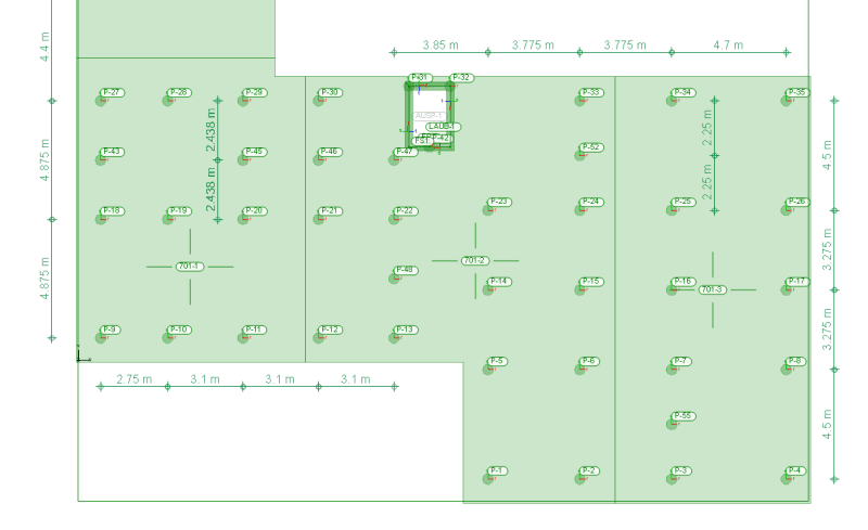
Here is an excerpt of the foundation that shows the layout, if it helps. Some indicated distances show that the critical perimeter of 2d overlap.
Most of the problematic piles are in a straight line, not sure how we can make a rectangle around them.
 
Effectively, I think that a lot of these "overlapping perimeter" situations will turn into one way shear situations with respect to multi-pile evaluation. This treatment was common in the past and can still be found in the latest edition of the CRSI design guide on piles I believe.
 
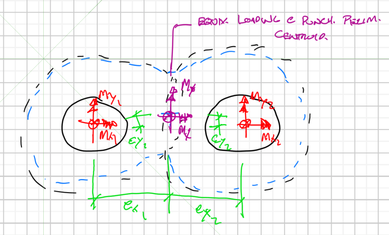
In close enough proximity I would think you need to work out:
- Centroid of the combined critical punch perimeter
- Static force transfer of the pile reactions/moments to the critical punch centroid

capture_aibehw.png


I'm making a thing: (It's no Kootware and it will probably break but it's alive!)
 
600mm slab - cover and half bar dia. say 600mm- 75mm (pile projection and point of load application) = 525 - cover (40mm) - mid point of bi driectioal bars. (say 20mm bars so 20mm) = 465. 2d = 930mm.

which ones are overlapping? they would need to be 1860 approx apart?

back to if they are. say piles are 500mm apart as a example. Add the two loads together. start the perimeter from the outside of each pile. so you have (in one direction 2D + the pile spacing). remember punching isnt calculting the actual shear stress that is present. its a way of representing how the load, in this case, is pushing up and creatign tension to 'punch' through. its not the same as calculating the shear on a beam. Its a fudge in effect based on testing and experimental work. you are never truly calculating the real shear stress at any point
 
Status
Not open for further replies.

Part and Inventory Search

Sponsor